- 您现在的位置:买卖IC网 > PDF目录21914 > A1354KKTTN-T (Allegro Microsystems Inc)IC HALL EFFECT SENSOR 2WIRE 4SIP PDF资料下载
参数资料
| 型号: | A1354KKTTN-T |
| 厂商: | Allegro Microsystems Inc |
| 文件页数: | 17/23页 |
| 文件大小: | 540K |
| 描述: | IC HALL EFFECT SENSOR 2WIRE 4SIP |
| 产品变化通告: | Product Obsolescence 09/Nov/2011 |
| 标准包装: | 4,000 |
| 传感范围: | 0.1% ~ 0.2%/G |
| 类型: | 线性场传感器 |
| 电源电压: | 4.5 V ~ 16 V |
| 电流 - 电源: | 9mA |
| 输出类型: | 数字式, PWM 编码 |
| 特点: | 高精度 |
| 工作温度: | -40°C ~ 125°C |
| 封装/外壳: | 4-SIP |
| 供应商设备封装: | 4-SIP |
| 包装: | 带卷 (TR) |
Programming Modes
Try Mode This mode allows multiple programmable parameters
to be tested simultaneously without permanently setting any
values. In this mode, each VPH pulse will indefinitely loop the
programming logic through the Mode Select, Register Select, and
Bitfield Select states, as long as there are no interruptions in the
VCC supply.
To enter Try mode, after powering the VCC supply and entering
the Initial state, send one VPH pulse to enter Mode Select state,
and then two VPM pulses (Mode Selection key 2).
Select the required parameter register and address its bitfield.
When addressing the bitfield, each VPM pulse increments the
value of the parameter register, up to the maximum possible
code (see the Programming Logic table). The addressed param-
eter value is stored in the device, even after the programming
drive voltage is removed from the VCC pin, allowing its value
to be measured. To test an additional programmable parameter
in conjunction with the original, enter an additional VPH pulse
on the VCC pin to re-enter the parameter selection field. Select
a different parameter register, and address its bitfield without
any supply interruptions. Both parameter values are stored and
can be measured after removing the programming drive voltage.
Multiple programming combinations can be tested to achieve
optimal application accuracy. See figure 6 for an example of the
Try mode pulse train.
When testing the device in Try mode, it is recommended to select
parameter register 4, the null register, before tests. This recom-
mendation is because the programming voltage levels overlap the
V
CC
operating levels, so varying V
CC
during tests in Try mode may
unintentionally result in device programming.
Registers can be addressed and re-addressed an indefinite
number of times, and in any order. After the required code is
found for each register, cycle the supply voltage and blow the
bitfield fuse using Blow mode. Note that for accurate time mea-
surements, the blow capacitor, C
BLOW
, should be removed during
output voltage measurement.
Blow Mode After the required value of the programmable
parameter is found using Try mode, the corresponding code
should be blown to make the value permanent. To do this, select
the required parameter register, and address and blow each
required bit separately (as described in the Fuse Blowing sec-
tion). The supply must be cycled between blowing each bit of a
given code. After a bit is blown, cycling the supply will not reset
its value.
Single parameters can still be addressed in Blow mode before
fuse blowing (simultaneous addressing of multiple parameters,
as in Try mode, is not possible). After powering the VCC supply,
select the required parameter register and address its bitfield.
When addressing the bitfield, each VPM pulse increments the
value of the parameter register, up to the maximum possible code
(see Programming Logic table). The addressed parameter value
is stored in the device, even after the programming drive voltage
is removed from the VCC pin, allowing its value to be measured.
Note that for accurate time measurements, the blow capacitor,
C
BLOW
, should be removed during output voltage measurement.
It is not possible to decrement the value of the register without
resetting the parameter bitfield. To reset the bit field, and thus the
value of the programmable parameter, cycle the supply voltage.
It is possible to switch between Try and Blow modes where
single programmable parameters can be blown in Blow mode
while other parameters can still be tested in Try mode.
Lock Mode To lock the device, address the LOCK bit, and
apply a blow pulse with C
BLOW
in place. After locking the
device, no future programming of any parameter is possible.
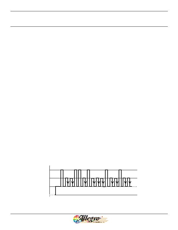
Figure 6. Example of Try mode programming pulses applied to the VCC pin. In this example, Sensitivity (Parameter Key 1) is
addressed to code 3, and D
(Q)
(Parameter Key 2) is addressed to code 2. The values set in the Sensitivity and D
(Q)
registers
are stored in the device until the supply is cycled. Permanent fuse blowing cannot be accomplished in Try mode.
V+
0
Mode Selection:
Try Mode
Parameter
Selection:
Sens/Coarse D
(Q)
(Key 2)
V
P(HIGH)
V
P(MID)
V
P(LOW)
(Key 1)
(Code 3)
Addressing
Bitfields 0 and 1
Parameter
Selection:
Fine D
(Q)
(Key 2)
(Code 2)
Addressing
Bitfield 1
1
2
1
2
1
2
1
1 2 3
High Precision 2-Wire Linear Hall Effect Sensor IC
with Pulse Width Modulated Output
A1354
16
Allegro MicroSystems, Inc.
115 Northeast Cutoff
Worcester, Massachusetts 01615-0036 U.S.A.
1.508.853.5000; www.allegromicro.com
相关PDF资料 |
PDF描述 |
|---|---|
| D2HW-C261M | SUBMINIATURE BASIC SWITCH |
| ATS643LSHTN-I1-T | IC SENSOR GEAR TOOTH 4-SIP |
| D2HW-C233M | SUBMINIATURE BASIC SWITCH |
| D2HW-C232MR | SUBMINIATURE BASIC SWITCH |
| D2HW-C232M | SUBMINIATURE BASIC SWITCH |
相关代理商/技术参数 |
参数描述 |
|---|---|
| A1354P1-2 | 制造商:APEM 功能描述: |
| A1354P1-6 | 功能描述:SWITCH HARDWARE RoHS:是 类别:开关 >> 配件 系列:- 标准包装:100 系列:- 其它名称:886.0007886.0007-ND |
| A1354P2-4 | 制造商:APEM 功能描述: |
| A1354P2-5 | 功能描述:SWITCH HARDWARE RoHS:是 类别:开关 >> 配件 系列:- 标准包装:100 系列:- 其它名称:886.0007886.0007-ND |
| A1355P1-2 | 制造商:APEM 功能描述: |
发布紧急采购,3分钟左右您将得到回复。