- 您现在的位置:买卖IC网 > PDF目录164966 > A165K-T2M-2 ROTARY SWITCH-2POSITIONS, DPDT, LATCHED, 3A, 30VDC, PANEL MOUNT PDF资料下载
参数资料
| 型号: | A165K-T2M-2 |
| 元件分类: | 开关 |
| 英文描述: | ROTARY SWITCH-2POSITIONS, DPDT, LATCHED, 3A, 30VDC, PANEL MOUNT |
| 文件页数: | 11/13页 |
| 文件大小: | 1882K |
| 代理商: | A165K-T2M-2 |
A165K
7
Specifications
Approved Standard Ratings
Ratings
Contacts
Minimum applicable load: 1 mA at 5 VDC
Rated values are obtained from tests conducted under the following conditions.
1. Load: Resistive load
2. Mounting conditions: No vibration and no shock
3. Temperature: 20
±2°C
4. Operating frequency: 20 times/min
Contact Form
Characteristics
Socket Units
Screw-less Clamp
Operating Characteristics
UL, cUL (File No. E41515)
TV (EN60947-5-1) (Low Voltage Directive)
CCC (GB14048.5)
5 A at 125 VAC, 3 A at 250 VAC (general use)
3 A at 30 VDC (resistive)
Note: Certification has been obtained for the Switch Unit.
For detailed information on individual products that
have received certification, consult your supplier.
3 A at 250 VAC
3 A at 30 VDC
5 A at 125 VAC
3 A at 250 VAC
3 A at 30 VDC
Rated voltage
Resistive load
125 VAC
5 A
250 VAC
3 A
30 VDC
3 A
Name
Contact form
SPDT
COM
NC
NO
Item
Type
Key-type Selector Switch
Allowable
operating
frequency
Mechanical
20 operations/minute max.
Electrical
10 operations/minute max.
Insulation resistance
100 M
min. (at 500 VDC)
Dielectric
strength
Between terminals
of same polarity
1,000 VAC, 50/60 Hz for 1 minute
Between terminals
of different polarity
2,000 VAC, 50/60 Hz for 1 minute
Between each ter-
minal and ground
2,000 VAC, 50/60 Hz for 1 minute
Vibration
resistance
Malfunction
10 to 55 Hz, 1.5-mm double amplitude
(malfunction within 1 ms)
Shock
resistance
Destruction
500 m/s2
Malfunction
150 m/s2 max. (malfunction within 1 ms)
Durability
Mechanical
250,000 operations min. (durability of key:
10,000 operations min.)
Electrical
100,000 operations min.
Electric shock protection
class
Class II
PTI (tracking characteristic)
175
Degree of contamination
3 (IEC60947-5-1)
Weight
Approx. 26.5 g (in the case of a DPDT
switch key)
Ambient operating
temperature
10
°C to 55°C
(with no icing or condensation)
Ambient operating humidity
35% to 85%RH
Ambient storage
temperature
25
°C to 65°C
(with no icing or condensation)
Item
Type
Screw-less Clamp
Recommended wire size
0.5 mm2 twisted wire or 0.8 mm-dia. solid wire
Usable
wires and
tensile
strength
Twisted wire
0.3 mm2
0.5 mm2
0.75 mm2
1.25 mm2
Solid wire
0.5 mm dia.
0.8 mm dia.
1.0 mm dia.
---
Tensile strength
10 N
20 N
30 N
40 N
Length of exposed wire
10
±1 mm
Compliant standards
JIS C 2811 Terminal Blocks for Industrial Use
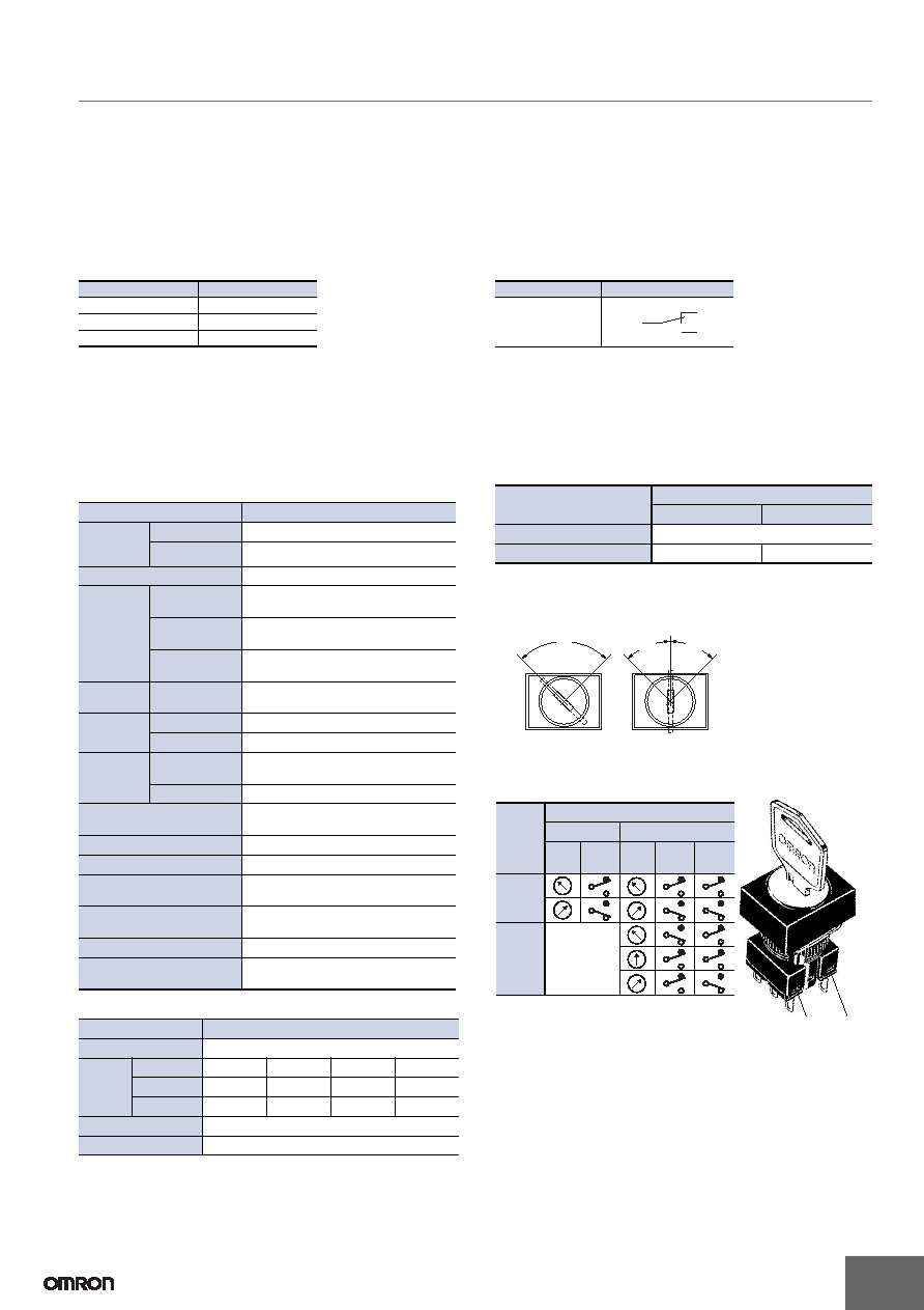
Type
Key-type Selector Switch
Characteristics
2 notches
3 notches
Operating force (OF) max.
0.1 Nm
Set position (SP)
90
±5°
45
°+10
0
Operation Angle
Note: The angle used for automatic reset is shown in parentheses.
FP: Free position
(75
°)
90
°
FP
45
°
(45
°)
45
°
(45
°)
Two notches
Three notches
SW1
SW2
Contact Configuration
No. of
notches
Contact configuration
SPDT
DPDT
Posi-
tion
SW
Posi-
tion
SW1
SW2
2
notches
3
notches
---
相关PDF资料 |
PDF描述 |
|---|---|
| A165L-JRA-5D-1 | PUSHBUTTON SWITCH, SPDT, ALTERNATE, 3A, 30VDC, PANEL MOUNT |
| A165L-AGM-5D-1 | PUSHBUTTON SWITCH, SPDT, MOMENTARY, 3A, 30VDC, PANEL MOUNT |
| A165L-JGM-5D-2 | PUSHBUTTON SWITCH, DPDT, MOMENTARY, 3A, 30VDC, PANEL MOUNT |
| A165L-JRM-12-1 | PUSHBUTTON SWITCH, SPDT, MOMENTARY, 3A, 30VDC, PANEL MOUNT |
| A16L-AGA-5-2 | PUSHBUTTON SWITCH, DPDT, ALTERNATE, 3A, 30VDC, PANEL MOUNT |
相关代理商/技术参数 |
参数描述 |
|---|---|
| A165KT2M2Q | 制造商:Omron Corporation 功能描述: |
| A165KT2M2S | 功能描述:键锁开关 KEYSS RND 2POS MNTD DPDT SCRLS RoHS:否 制造商:C&K Components 触点形式:1 Form A (SPST-NO) 开关功能:Momentary 触点额定值: 电流额定值:100 mA 电压额定值 AC:250 VAC 端接类型:Through Hole 键类型:Keyswitch 变址: 位置数量:1 外壳材料: |
| A165K-T2M-2S | 制造商:Omron Corporation 功能描述:Keylock Switches KEYSS RND 2POS MNTD DPDT SCRLS |
| A165KT2ML | 制造商:OMRON AUTOMATION AND SAFETY 功能描述:SWITCH UNIT ROUND ALT 2POS 制造商:OMRON INDUSTRIAL AUTOMATION 功能描述:Switch Access Keylock Switch Round Selector |
| A165K-T2ML | 功能描述:键锁开关 RND 2POS MAINT LEFT Key Selector Switch RoHS:否 制造商:C&K Components 触点形式:1 Form A (SPST-NO) 开关功能:Momentary 触点额定值: 电流额定值:100 mA 电压额定值 AC:250 VAC 端接类型:Through Hole 键类型:Keyswitch 变址: 位置数量:1 外壳材料: |
发布紧急采购,3分钟左右您将得到回复。