- 您现在的位置:买卖IC网 > PDF目录57457 > A3340LLHLT-T MAGNETIC FIELD SENSOR-HALL EFFECT, 0.5-5mT, 270-500mV, RECTANGULAR, SURFACE MOUNT PDF资料下载
参数资料
| 型号: | A3340LLHLT-T |
| 元件分类: | 磁阻传感器 |
| 英文描述: | MAGNETIC FIELD SENSOR-HALL EFFECT, 0.5-5mT, 270-500mV, RECTANGULAR, SURFACE MOUNT |
| 封装: | LEAD FREE, SOT-23W, 3-PIN |
| 文件页数: | 7/9页 |
| 文件大小: | 257K |
| 代理商: | A3340LLHLT-T |
Chopper-Stabilized, Precision Hall-Effect Switch
A3340
7
Allegro MicroSystems, Inc.
115 Northeast Cutoff, Box 15036
Worcester, Massachusetts 01615-0036 (508) 853-5000
www.allegromicro.com
Dwg. EH-012
REG
X
SAMPLE
&
HOLD
+V CC
B
–VHALL
+VHALL
+B
0
FL UX DE NS IT Y
0
B
CC
V
B
+V
OP
RP
O
U
TP
U
T
VO
L
T
AG
E
V OUT(S AT)
SUPPLY
OUTPUT
Dwg. EH-013
0.1 μF
SUPPLY
X
PTCT
VCC
GND
VOUT
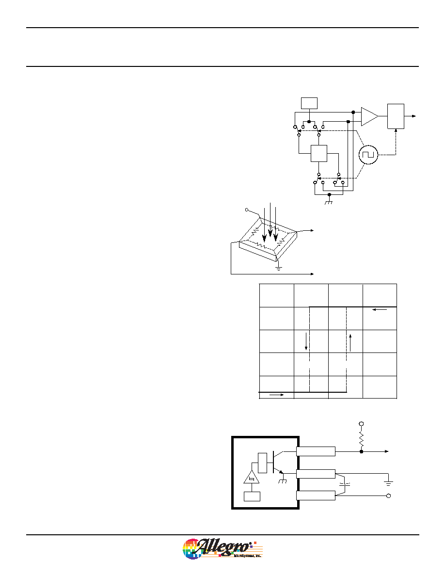
Chopper-Stabilized Technique. The Hall element can be
considered as a resistor array similar to a Wheatstone bridge. A
large portion of the offset is a result of the mismatching of these
resistors. These devices use a proprietary dynamic offset cancel-
lation technique, with an internal high-frequency clock to reduce
the residual offset voltage of the Hall element that is normally
caused by device overmolding, temperature dependencies, and
thermal stress. The chopper-stabilizing technique cancels the
mismatching of the resistor circuit by changing the direction of
the current flowing through the Hall plate using CMOS switches
and Hall voltage measurement taps, while maintaing the Hall-
voltage signal that is induced by the external magnetic flux. The
signal is then captured by a sample-andhold circuit and further
processed using low-offset bipolar circuitry. This technique pro-
duces devices that have an extremely stable quiescent Hall output
voltage, are immune to thermal stress, and have precise recover-
ability after temperature cycling. This technique will also slightly
degrade the device output repeatability. A relatively high sampling
frequency is used in order that faster signals can be processed.
More detailed descriptions of the circuit operation can be found
in: Technical Paper STP 97-10, Monolithic Magnetic Hall Sensor
Using Dynamic Quadrature Offset Cancellation and Technical
Paper STP 99-1, Chopper-Stabilized Amplifiers With A Track-and-
Hold Signal Demodulator. Operation. The output of these devices
switches high (turns off) when a magnetic field (south pole)
perpendicular to the Hall sensor exceeds the operate point thresh-
old (BOP). When the magnetic field is reduced below the release
point (BRP), the device output goes low (turns on). After turn-on,
the output is capable of sinking 25 mA and the output voltage is
VOUT(SAT). The difference in the magnetic operate and release
points is the hysteresis (Bhys) of the device. This built-in hyster-
esis allows clean switching of the output even in the presence of
external mechanical vibration and electrical noise. Applications.
It is strongly recommended that an external bypass capacitor be
connected (in close proximity to the Hall sensor) between the
supply and ground of the device to reduce both external noise and
noise generated by the chopperstabilization technique.
The simplest form of magnet that will operate these devices is a
ring magnet. Other methods of operation, such as linear magnets,
are possible. Extensive applications information on magnets and
Hall-effect sensors is also available in Application Note 27701, or
at www.allegromicro.com.
FUNCTIONAL DESCRIPTION
相关PDF资料 |
PDF描述 |
|---|---|
| A3422LKA | MAGNETIC FIELD SENSOR-HALL EFFECT, -85-85mT, 0.21-0.50V, RECTANGULAR, THROUGH HOLE MOUNT |
| A3507EU | MAGNETIC FIELD SENSOR-HALL EFFECT, 35mT, 0.50-4.80V, RECTANGULAR, THROUGH HOLE MOUNT |
| A3507EU | MAGNETIC FIELD SENSOR-HALL EFFECT, 3.5mT, RECTANGULAR |
| A3507LUA | MAGNETIC FIELD SENSOR-HALL EFFECT, 35mT, 4.50-4.80V, RECTANGULAR, THROUGH HOLE MOUNT |
| A3508EUA | MAGNETIC FIELD SENSOR-HALL EFFECT, 35mT, 4.50-4.80V, RECTANGULAR, THROUGH HOLE MOUNT |
相关代理商/技术参数 |
参数描述 |
|---|---|
| A3340LUA-T | 功能描述:IC HALL EFFECT SWITCH 3-SIP RoHS:是 类别:传感器,转换器 >> 磁性 - 霍尔效应,数字式开关,线性,罗盘 (IC) 系列:- 标准包装:1 系列:- 传感范围:20mT ~ 80mT 类型:旋转 电源电压:4.5 V ~ 5.5 V 电流 - 电源:15mA 电流 - 输出(最大):- 输出类型:数字式,PWM,8.5 位串行 特点:可编程 工作温度:-40°C ~ 150°C 封装/外壳:20-SSOP(0.209",5.30mm 宽) 供应商设备封装:20-SSOP 包装:Digi-Reel® 其它名称:AS5132-HSST-500DKR |
| A3342B | 制造商: 功能描述: 制造商:New Japan Radio Co Ltd (NJR/JRC) 功能描述: 制造商:undefined 功能描述: |
| A33463-000 | 功能描述:可复位保险丝 RoHS:否 制造商:TE Connectivity / Raychem 电流额定值: 电阻:0.08 Ohms (max) 最大直流电压: 保持电流:2.5 A 安装风格:Through Hole 端接类型: 跳闸电流:5 A 引线间隔: 系列:RXEF 工作温度范围:+ 85 C |
| A33466-000 | 制造商:TE Connectivity 功能描述:VARISTOR 200V 7MM STRAIGHT LEAD 制造商:TE Connectivity 功能描述:VARISTOR 200V 1.75KA DISC 7MM |
| A33485-000 | 制造商:TE Connectivity 功能描述:VARISTOR 680V 6KA DISC 14MM 制造商:TE Connectivity 功能描述:VARISTOR 680VDC 14MM 10% LEADED |
发布紧急采购,3分钟左右您将得到回复。