- 您现在的位置:买卖IC网 > PDF目录1773 > A4975SB-T (Allegro Microsystems Inc)IC PWM MICROSTEP DVR FULL 16DIP PDF资料下载
参数资料
| 型号: | A4975SB-T |
| 厂商: | Allegro Microsystems Inc |
| 文件页数: | 6/13页 |
| 文件大小: | 0K |
| 描述: | IC PWM MICROSTEP DVR FULL 16DIP |
| 特色产品: | A4975 Microstepping Drivers |
| 标准包装: | 7,500 |
| 应用: | PWM 电机驱动器,步进电机驱动器 |
| 输出数: | 1 |
| 电流 - 输出: | 1.5A |
| 电压 - 负载: | 5 V ~ 50 V |
| 电源电压: | 4.5 V ~ 5.5 V |
| 工作温度: | -20°C ~ 85°C |
| 安装类型: | 通孔 |
| 封装/外壳: | 16-DIP(0.300",7.62mm) |
| 供应商设备封装: | 16-DIP |
| 包装: | 管件 |
| 其它名称: | 620-1435-5 A4975SB-T-ND |
�� �
�
�A4975�
�Full-Bridge� PWM� Microstepping� Motor� Driver�
�Functional� Description�
�Two� A4975� full-bridge� PWM� microstepping� motor� drivers� are�
�needed� to� drive� the� windings� of� a� bipolar� stepper� motor.� Internal�
�pulse� width� modulated� (PWM)� control� circuitry� regulates� each�
�motor� winding� current.� The� peak� motor� current� is� set� by� the�
�value� of� an� external� current-sense� resistor� (R� S� ),� a� reference�
�voltage� (V� REF� ),� and� the� digital-to-analog� converter� (DAC)� data�
�inputs� (D� 0� ,� D� 1� ,� and� D� 2� ).�
�To� improve� motor� performance,� especially� when� using�
�sinusoidal� current� pro� ?� les� necessary� for� microstepping,� the�
�A4975� has� three� distinct� current-decay� modes:� slow� decay,� fast�
�decay,� and� mixed� decay.�
�PHASE� Input.� The� PHASE� input� controls� the� direction� of�
�current� ?� ow� in� the� load� (table� 1).� An� internally� generated� dead�
�time� of� approximately� 500� ns� prevents� crossover� currents� that�
�could� occur� when� switching� the� PHASE� input.�
�DAC� Data� Inputs� (D� 0� ,� D� 1� ,� D� 2� ).� A� non-linear� DAC� is� used�
�to� digitally� control� the� output� current.� The� output� of� the� DAC� is�
�used� to� set� the� trip� point� of� the� current-sense� comparator.� Table� 3�
�shows� DAC� output� voltages� for� each� input� condition.� When� D� 0� ,�
�D� 1� ,� and� D� 2� are� all� logic� low,� all� of� the� power� output� transistors�
�are� turned� off.�
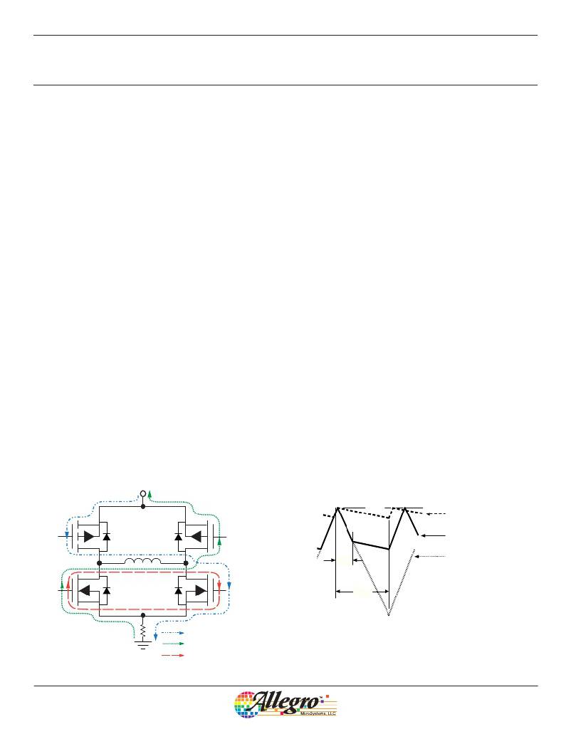
�Internal� PWM� Current� Control.� Each� motor� driver�
�contains� an� internal� ?� xed� off-time� PWM� current-control� circuit�
�that� limits� the� load� current� to� a� desired� value� (I� TRIP� ).� Initially,�
�a� diagonal� pair� of� source� and� sink� transistors� are� enabled� and�
�current� ?� ows� through� the� motor� winding� and� R� S� (� ?� gure� 1).� When�
�the� voltage� across� the� sense� resistor� equals� the� DAC� output�
�voltage� the� current-sense� comparator� resets� the� PWM� latch,�
�V� BB�
�which� turns� off� the� source� drivers� (slow-decay� mode)� or� the� sink�
�and� source� drivers� (fast-� or� mixed-decay� mode).�
�With� the� DAC� data� input� lines� at� V� IN(1)� voltage,� the� maximum�
�value� of� current� limiting� is� set� by� the� selection� of� R� S� and� V� REF�
�with� a� transconductance� function� approximated� by:�
�I� TRIP� ≈� V� REF� /� 5R� S� .�
�The� actual� peak� load� current� (I� PEAK� )� will� be� slightly� higher� than�
�I� TRIP� due� to� internal� logic� and� switching� delays.� The� driver(s)�
�remain� off� for� a� time� period� determined� by� a� user-selected�
�external� resistor-capacitor� combination� (R� T� C� T� ).� At� the� end� of�
�the� ?� xed� off-time,� the� driver(s)� are� re-enabled,� allowing� the� load�
�current� to� increase� to� I� TRIP� again,� maintaining� an� average� load�
�current.�
�The� DAC� data� input� lines� are� used� to� provide� up� to� eight� levels�
�of� output� current.� The� internal� 3-bit� digital-to-analog� converter�
�reduces� the� reference� input� to� the� current-sense� comparator�
�in� precise� steps� (the� step� reference� current� ratio� or� SRCR)� to�
�provide� half-step,� quarter-step,� or� “microstepping”� load-current�
�levels.�
�I� TRIP� ≈� SRCR� x� V� REF� /� 5R� S�
�Slow� Current-Decay� Mode.� When� V� PFD� ≥� 3.5� V,� the�
�device� is� in� slow� current-decay� mode� (the� source� drivers� are�
�disabled� when� the� load� current� reaches� I� TRIP� ).� During� the� ?� xed�
�off-time,� the� load� inductance� causes� the� current� to� recirculate�
�through� the� motor� winding� and� sink� drivers� (see� ?� gure� 1).�
�Slow-decay� mode� produces� low� ripple� current� for� a� given� ?� xed�
�off-time� (see� ?� gure� 2).� Low� ripple� current� is� desirable� because�
�the� average� current� in� the� motor� winding� is� more� nearly� equal�
�to� the� desired� reference� value,� resulting� in� increased� motor�
�PFD�
�I� PEAK�
�SLOW� (V� PFD� ≥� 3.5� V)�
�MIXED� (1.1� V� ≤� V� PFD� ≤� 3.1� V)�
�FAST� (V� PFD� ≤� 0.8� V)�
�t� OFF�
�Dwg.� WP-031-1�
�R� S�
�Drive� Current� (Normal)�
�Recirculation� (Fast� Decay)�
�Recirculation� (Slow� Decay)�
�Figure� 1� —� Load-Current� Paths�
�Figure� 2� —� Current-Decay� Waveforms�
�Allegro� MicroSystems,� LLC�
�115� Northeast� Cutoff�
�Worcester,� Massachusetts� 01615-0036� U.S.A.�
�1.508.853.5000;� www.allegromicro.com�
�6�
�相关PDF资料 |
PDF描述 |
|---|---|
| A4979GLPTR-T | IC MOTOR DRVR MICRO STEP 28TSSOP |
| A4980KLPTR-T | IC STEPPER DVR PROGR 28-TSSOP |
| A4982SLPTR-T | IC DRIVER MICROSTEPPING 24-TSSOP |
| A4983SETTR-T | IC MOTOR DRIVER MICROSTEP 28-QFN |
| A4984SLPTR-T | IC STEPPER MOTOR DRIVER 24TSSOP |
相关代理商/技术参数 |
参数描述 |
|---|---|
| A4975SLBTR-T | 功能描述:IC PWM MICROSTEP DVR FULL 16SOIC RoHS:是 类别:集成电路 (IC) >> PMIC - 电机和风扇控制器,驱动器 系列:- 产品变化通告:ATA683(3,4)PLQW Obsolescence 09/Aug/2012 标准包装:1 系列:- 应用:DC 电机控制器,无刷(BLDC),3 相 评估套件:可供 输出数:1 电流 - 输出:100mA 电压 - 负载:5.25 V ~ 20 V 电源电压:5.25 V ~ 20 V 工作温度:-40°C ~ 150°C 安装类型:表面贴装 封装/外壳:48-VFQFN 裸露焊盘 供应商设备封装:48-VQFN(7x7) 包装:剪切带 (CT) 其它名称:ATA6833-PLQWCT |
| A4979 | 制造商:ALLEGRO 制造商全称:Allegro MicroSystems 功能描述:The A4979 is a flexible microstepping motor driver with built-in translator for easy operation. |
| A4979GLPTR-T | 功能描述:IC MOTOR DRVR MICRO STEP 28TSSOP RoHS:是 类别:集成电路 (IC) >> PMIC - 电机和风扇控制器,驱动器 系列:- 标准包装:1 系列:- 应用:步进电机驱动器,1-2 相,2 相 评估套件:- 输出数:1 电流 - 输出:800mA 电压 - 负载:10 V ~ 28 V 电源电压:4.75 V ~ 5.25 V 工作温度:-20°C ~ 90°C 安装类型:表面贴装 封装/外壳:28-SOP + 2 翼片裸露焊盘 供应商设备封装:28-HSOPHC(15.2x7.9) 包装:剪切带 (CT) 其它名称:869-1268-1 |
| A4980 | 制造商:ALLEGRO 制造商全称:Allegro MicroSystems 功能描述:The A4980 is a flexible microstepping motor driver with built-in translator for easy operation. |
| A4980KLP-T | 制造商:Allegro MicroSystems LLC 功能描述: |
发布紧急采购,3分钟左右您将得到回复。