- 您现在的位置:买卖IC网 > PDF目录375144 > A61L73081 (AMIC Technology Corporation) 128K X 8 BIT HIGH SPEED CMOS SRAM PDF资料下载
参数资料
| 型号: | A61L73081 |
| 厂商: | AMIC Technology Corporation |
| 英文描述: | 128K X 8 BIT HIGH SPEED CMOS SRAM |
| 中文描述: | 128K的× 8位高速CMOS SRAM的 |
| 文件页数: | 4/12页 |
| 文件大小: | 180K |
| 代理商: | A61L73081 |
A61L73081 Series
(April, 2001, Version 1.0)
3
AMIC Technology, Inc.
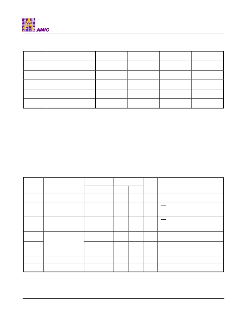
Recommended DC Operating Conditions
(T
A
= 0
°
C to + 70
°
C)
Symbol
Parameter
Min.
Typ.
Max.
Unit
VCC
Supply Voltage
3.0
3.3
3.6
V
GND
Ground
0
0
0
V
V
IH
Input High Voltage
2.2
-
VCC + 0.5
V
V
IL
Input Low (1) Voltage
-0.5
0
+0.8
V
C
L
Output Load
-
-
30
pF
Absolute Maximum Ratings*
VCC to GND . . . . . . . . . . . . . . . . . . . . . . . -0.5V to +4.6V
IN, IN/OUT Volt to GND . . . . . . . . . . -0.5V to VCC +0.5V
Operating Temperature, Topr . . . . . . . . . . . 0
°
C to +70
°
C
Storage Temperature, Tstg . . . . . . . . . . -55
°
C to +125
°
C
Temperature Under Bias, Tbias . . . . . . . . -10
°
C to +85
°
C
Power Dissipation, P
T
. . . . . . . . . . . . . . . . . . . . . . . 0.7W
*Comments
Stresses above those listed under "Absolute Maximum
Ratings" may cause permanent damage to this device.
These are stress ratings only. Functional operation of this
device at these or any other conditions above those
indicated in the operational sections of this specification is
not implied or intended. Exposure to the absolute maximum
rating conditions for extended periods may affect device
reliability.
DC Electrical Characteristics
(T
A
= 0
°
C to + 70
°
C, VCC = 3.3V
±
10%, GND = 0V)
Symbol
Parameter
A61L73081-12
A61L73081-15
Unit
Conditions
Min.
Max.
Min.
Max.
I
LI
Input Leakage
-
2
-
2
μ
A
V
IN
= GND to VCC
I
LO
Output Leakage
-
2
-
2
μ
A
CE = V
IH
, OE = V
IH
V
I/O
= GND to VCC
I
CC1
(2)
Dynamic Operating
Current
-
220
-
210
mA
CE = V
IL
, I
I/O
= 0 mA
Min. Cycle, Duty = 100%
I
SB
-
25
-
25
mA
CE = V
IH
I
SB1
Standby Power
Supply Current
-
12
-
12
mA
CE
≥
VCC - 0.2V,
V
IN
≥
VCC -0.2V or V
IN
≤
0.2V
V
OL
Output Low Voltage
-
0.4
-
0.4
V
I
OL
= 8 mA
V
OH
Output High Voltage
2.4
-
2.4
-
V
I
OH
= -4 mA
Notes: 1. V
IL
= -3.0V for pulses less than 20 ns.
2. I
CC1
is dependent on output loading, cycle rates, and Read/Write patterns.
相关PDF资料 |
PDF描述 |
|---|---|
| A61L73081S-12 | 128K X 8 BIT HIGH SPEED CMOS SRAM |
| A61L73081S-15 | 128K X 8 BIT HIGH SPEED CMOS SRAM |
| A61L73081SW-12 | 128K X 8 BIT HIGH SPEED CMOS SRAM |
| A61L73081SW-15 | 128K X 8 BIT HIGH SPEED CMOS SRAM |
| A623308A | 8K X 8 BIT CMOS SRAM |
相关代理商/技术参数 |
参数描述 |
|---|---|
| A61L73081S-12 | 制造商:AMICC 制造商全称:AMIC Technology 功能描述:128K X 8 BIT HIGH SPEED CMOS SRAM |
| A61L73081S-15 | 制造商:AMICC 制造商全称:AMIC Technology 功能描述:128K X 8 BIT HIGH SPEED CMOS SRAM |
| A61L73081SW-12 | 制造商:AMICC 制造商全称:AMIC Technology 功能描述:128K X 8 BIT HIGH SPEED CMOS SRAM |
| A61L73081SW-15 | 制造商:AMICC 制造商全称:AMIC Technology 功能描述:128K X 8 BIT HIGH SPEED CMOS SRAM |
| A61P21N | 制造商:Pentair Technical Products / Hoffman 功能描述:Panel, NEMA 1 White, fits 72.00x25.5/26, Steel |
发布紧急采购,3分钟左右您将得到回复。