- 您现在的位置:买卖IC网 > PDF目录364584 > A6802 Gigabit Dual Transformers - For Use with 150 Ohm Twinax Cable (1/99) PDF资料下载
参数资料
| 型号: | A6802 |
| 英文描述: | Gigabit Dual Transformers - For Use with 150 Ohm Twinax Cable (1/99) |
| 中文描述: | 千兆双变压器-为150欧姆屏蔽双绞线电缆(1 / 99使用) |
| 文件页数: | 2/2页 |
| 文件大小: | 50K |
| 代理商: | A6802 |
1.
R1 and R2 values should be based upon the transmit
amplitude required for the system. Placing a short
(0
) will result in maximum amplitude. However,
doing so will result in distortion on the output due to
impedance mismatch. For optimum design, R1 and
R2 should be approximately 68
for each leg. This
will result in a -6.0 dB insertion loss (transmitter
section). If this is too much insertion loss, then at
least a 15
for R1 and R2 is recommended.
Insertion Loss of Transmitter:
Req = R1 + R2 and Zo = 150
Insertion Loss = 20 log [Zo / Req + Z0]
2.
When designing PCB layout, transmission line
methods must be utilized to maintain return loss and
signal integrity. Transformer should be located within
1" of cable connector.
tr
transformer
=
√
[ (tr
out
)
2
- (tr
in
)
2
]
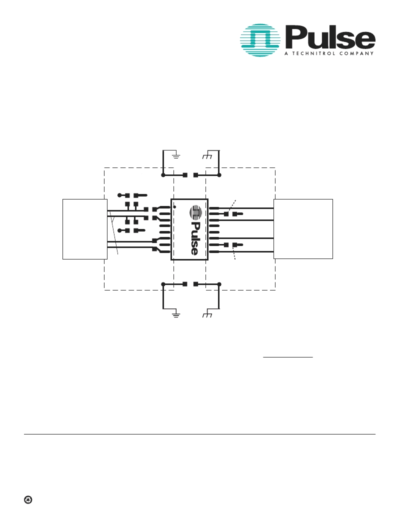
The typical application circuit shown above is a sug-
gested layout. Actual board layout may vary based
upon individual applications and EMC concerns.
NOTE:
These gigabit dual transformers are packaged in tubes unless Tape &
Reel is specified. When ordering, add the suffix
“T”
(i.e. A6801
T
) for
“Tape & Reel”
packaging in increments of 500.
3.
4.
For More Information :
Corporate
12220 World Trade Drive
San Diego, CA 92128
Tel:
619 674 8100
FAX: 619 674 8262
http://www.pulseeng.com
Quick-Facts: 619 674 9672
Performance warranty of products offered on this data sheet is limited to the parameters specified. Data is subject to change without notice. Other brand and product
names mentioned herein may be trademarks or registered trademarks of their respective owners.
Printed on recycled paper. 1999, Pulse Engineering, Inc.
Europe
1 & 2 Huxley Road
The Surrey Research Park
Guildford, Surrey GU2 5RE
United Kingdom
Tel:
44 1483 401700
FAX: 44 1483 401701
Asia
150 Kampong Ampat
#07-01/02
KA Centre
Singapore 368324
Tel: 65 287 8998
FAX: 65 280 0080
Distributor
GIGABIT DUAL
TRANSFORMERS
For Use with 150
Twinax Cable
A100.A (1/99)
Application Notes:
Pulse has designed Gigabit Dual Transformers speci-
fically for point to point coupling to 150
Twinax cable.
The isolation transformers protect the station from static
charges that may develop on the cable and prevent
ground loop currents from being transferred between
stations. The devices have also been designed to provide
common mode rejection within the transmission band and
thus reduce EMI. The bandwidth of these devices
minimizes data dependent jitter by providing fast signal
rise times. The dual package allows connection of both
the transmit and receive channels as shown in the
application circuit below. Surface mount packaging also
allows a cost effective solution. The transformers are
available in either tubes or Tape & Reel packaging.
C3
Chassis Gnd.
D.C. Gnd.
C4
SERDES
CHIP SET
HSDCC OR DB9
CONNECTOR
VCC GND
120 200
VCC
GND
75
TRANSMISSION LINES
Chassis Gnd.
D.C. Gnd.
TX+
TX-
RX-
RX+
R1
Chassis Gnd.
Chassis Gnd.
C1
.027 μF
C2
.027 μF
TX+
TX-
RX-
RX+
A
D
150
R2
120 200
相关PDF资料 |
PDF描述 |
|---|---|
| A6812KA | VACUUM FLUORESCENT DISPLAY DRIVER|BICMOS|DIP|28PIN|PLASTIC |
| A6812KEP | VACUUM FLUORESCENT DISPLAY DRIVER|BICMOS|LDCC|28PIN|PLASTIC |
| A6812KLW | VACUUM FLUORESCENT DISPLAY DRIVER|BICMOS|SOP|28PIN|PLASTIC |
| A6812XEP | DABiC-IV. 20-BIT SERIAL-INPUT. LATCHED SOURCE DRIVER |
| A6A6812ELW | DABiC-IV. 20-BIT SERIAL-INPUT. LATCHED SOURCE DRIVER |
相关代理商/技术参数 |
参数描述 |
|---|---|
| A6802NL | 制造商:Pulse 功能描述:TRANSFORMER - Bulk |
| A6802NLT | 制造商:Pulse Electronics Corporation 功能描述:Telecom Transformer 1:1 0.21Ohm Prim. DCR 16Term. Gull Wing SMD 制造商:Pulse Electronics Corporation 功能描述:Telecom Transformer 1:1 1500Vrms 0.21Ohm Prim. DCR Surface Mount |
| A6805 | 制造商:EPCOS 制造商全称:EPCOS 功能描述:AC Film Capacitors Lighting |
| A68089-000 | 制造商:TE Connectivity 功能描述:ZH2-9.0-0-FSP-SM - Cable Rools/Shrink Tubing 制造商:TE Connectivity 功能描述:HEATSHRINK TUBING 1=500 METERS |
| A6809 | 制造商:ALLEGRO 制造商全称:Allegro MicroSystems 功能描述:DABiC-IV, 10-BIT SERIAL-INPUT, LATCHED SOURCE DRIVERS |
发布紧急采购,3分钟左右您将得到回复。