- 您现在的位置:买卖IC网 > PDF目录364590 > AB-144 AB-144 - NEW SOFTWARE FOR THE DDC112 EVALUATION FIXTURE PDF资料下载
参数资料
| 型号: | AB-144 |
| 英文描述: | AB-144 - NEW SOFTWARE FOR THE DDC112 EVALUATION FIXTURE |
| 中文描述: | 抗体- 144 -新的DDC112评价夹具软件 |
| 文件页数: | 2/2页 |
| 文件大小: | 50K |
| 代理商: | AB-144 |
2
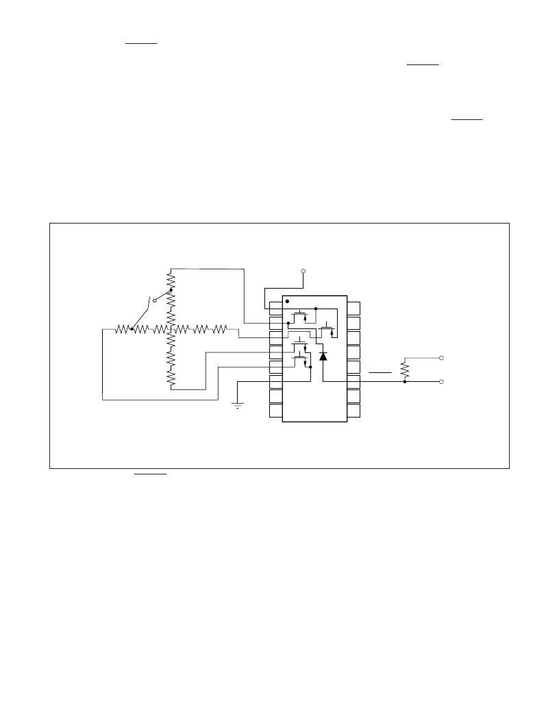
Figure 2 shows a simplified schematic of the ADS7843 front
end while using the PENIRQ. The resistive touch-screen is
represented with the row and column of series resistors
between the X and Y inputs. The switch, S1, models a
dynamic short that moves across the X and Y resistive touch-
screen axes like the tip of a PDA pen. S1 also models where
the tip of the PDA pen initially shorts the two resistive layers
together. I/O1 and I/O2 are general purpose input/output
ports from the MPU. I/O2 must be able to sense a change in
potential when powered down.
Be sure to note that the ADC will not start in the power-down
mode when power is applied to the system. Instead, the
MPU must write zeros into PD0 and PD1—two bits of the
Control Byte register. After the ADS7843 enters the power-
down mode, the Y-MOSFET provides a path for current flow
when the touch-screen is depressed. The other three
MOSFETs for X+, X–, and Y+ are in a high impedance state
during the power-down mode. When the PDA pen depresses
the touch-screen, current flows through the 100k
resistor
and the interrupt diode. Once PENIRQ is pulled LOW, a
voltage typically not exceeding 0.65V is sensed at I/O2. At
that time, the MPU should wake up, pull I/O1 and I/O2
LOW, then write a byte to the ADS7843 Control Byte
register to initiate a conversion. The MPU must drive I/O1
and I/O2 LOW in order to reverse bias the PENIRQ diode.
Otherwise, if the diode is forward-biased during a conver-
sion, the additional current will cause the input data to be
inaccurate. To complete the control cycle, the MPU writes
the corresponding power-down bits to the ADS7843 Control
Byte after the PDA has no inputs for a minute or two,
depending on the time allotted prior to the power-down
operation.
100k
S
1
PENIRQ
X+
Y+
X–
Y–
I/O1
I/O2
ADS7843
V
CC
FIGURE 2. Simplified PENIRQ Architecture.
相关PDF资料 |
PDF描述 |
|---|---|
| AB-146 | AB-146 - USING THE ADS1201 EVALUATION BOARD |
| AB-147 | AB-147 - Control Port and Reset Operation for Burr-Brown SoundPlus Audio Converters and CODECs |
| AB-148 | AB-148 - Low Sampling Rate Operation For Burr-Brown SoundPlus Audio Data Converters And CODECs |
| AB-150 | AB-150 - CREATING A BIPOLAR INPUT RANGE FOR THE DDC112 |
| AB-151 | AB-151 - FOUR-WIRE RTD CURRENT-LOOP TRANSMITTER: Four-Wire Connections to an RTD Allow the RTD to be Remotely Located from Active Circuitry. Yet Maintain Accuracy |
相关代理商/技术参数 |
参数描述 |
|---|---|
| AB144/440C | 功能描述:ANT A-BASE VHF 38" CHROME RoHS:是 类别:RF/IF 和 RFID >> RF 天线 系列:- 标准包装:1 系列:* |
| AB-146 | 制造商:未知厂家 制造商全称:未知厂家 功能描述:AB-146 - USING THE ADS1201 EVALUATION BOARD |
| AB14-6A | 制造商:Thomas & Betts 功能描述:Flag Terminal 14-22AWG 13.97mm 7.87mm |
| AB-147 | 制造商:未知厂家 制造商全称:未知厂家 功能描述:AB-147 - Control Port and Reset Operation for Burr-Brown SoundPlus Audio Converters and CODECs |
| AB-148 | 制造商:未知厂家 制造商全称:未知厂家 功能描述:AB-148 - Low Sampling Rate Operation For Burr-Brown SoundPlus Audio Data Converters And CODECs |
发布紧急采购,3分钟左右您将得到回复。