- 您现在的位置:买卖IC网 > Datasheet目录202 > ACA-20RM-5-AC3-RL-ALM-C (Murata Power Solutions Inc)AMMETER AC 30A 120V W/ALARM RED Datasheet资料下载
参数资料
| 型号: | ACA-20RM-5-AC3-RL-ALM-C |
| 厂商: | Murata Power Solutions Inc |
| 文件页数: | 3/5页 |
| 文件大小: | 0K |
| 描述: | AMMETER AC 30A 120V W/ALARM RED |
| 产品目录绘图: | Digital Panel Meter |
| 特色产品: | ACA-20RM-ALM Series Ammeters |
| 标准包装: | 12 |
| 系列: | ACA-20RM-ALM |
| 类型: | 安培表 |
| 测量范围: | 0 ~ 30.0A |
| 显示器样式: | 红色字符,黑色背景 |
| 显示器类型: | LED |
| 显示器位数: | 3.5 |
| 显示器位数 - 高度: | 0.370"(9.40mm) |
| 背光: | 无 |
| 安装类型: | 面板安装 |
| 端子: | 端接块 |
| 电源电压: | 85 ~ 140VAC |
| 产品目录页面: | 2856 (CN2011-ZH PDF) |
| 其它名称: | 811-1982 |
�� �
�
�ACA-20RM-ALM� Series�
�True-rms-AC� Ammeters� with� Alarm� Function�
�To� adjust� the� overcurrent� alarm� set-point� level:�
�A.� Turn� off� power� to� the� ACA-20RM-ALM� (i.e.,� the� power� source� con-�
�nected� to� TB1).�
�B.� Carefully� remove� the� shorting� jumper� across� JP1� from� its� ‘normal�
�operation� position’� across� terminals� 2� and� 3� and� place� it� across� JP1�
�terminals� 1� and� 2.�
�C.� Re-apply� power� to� TB1� and,� using� a� plastic� insulated� adjusting� tool,�
�adjust� R3� so� the� ammeter’s� display� shows� the� desired� overcurrent�
�trip� level� in� Amps.�
�D.� Turn� off� power� to� the� ACA-20RM-ALM� and� return� JP1’a� shorting�
�jumper� back� to� its� ‘normal� operation� position’� across� terminals� 2�
�and� 3.� Re-apply� power� to� TB1� to� resume� normal� operation.� If� pos-�
�sible,� after� the� ammeter� is� re-con?gured� for� normal� operation,� the�
�load� current� should� be� slowly� increased� to� verify� the� visual� alarm�
�operates� when� the� load� current� exceeds� the� preset� level.�
�Please� note,� the� load� circuit� does� not� need� to� be� turned� off� to� adjust� the�
�overcurrent� alarm� set� point.� Current� ?owing� through� L1� while� JP1� is�
�across� terminals� 1� and� 2� will� not� be� measured.� Once� tripped,� the� alarm�
�7.� Isolation:� The� built-in� current� transformer� L1� provides� a� minimum�
�of� 2000Vdc� isolation� between� the� load� conductor� and� the� ammeter’s�
�supply� voltage� connected� to� TB1.�
�8.� Split-Core� CT� (Clamp-on)� Models:� Both� 50A� models� feature� a� split-�
�core� current� transformer� that� can� be� clamped� around� a� properly� insu-�
�lated� live� conductor� without� having� to� disconnect� or� remove� power�
�from� the� load� circuit.� This� live-connection� capability� can� only� be� used�
�if� the� load’s� power� source� is� electrically� isolated� (see� technical� note�
�7)� from� the� ammeter’s� own� power� source� that’s� connected� to� TB1.�
�The� ammeter’s� ac� power� supply� must� always� be� denergized� before�
�making� connections� to� TB1.� Refer� to� the� ‘Panel� Installation’� section� of�
�this� data� sheet� for� additional� information.�
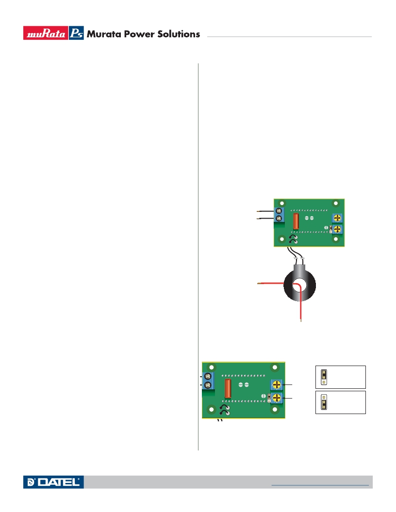
�BACK� VIEW�
�A�
�set� point� function� has� a� hysteresis� of� approximately� 0.5A.�
�The� overcurrent� alarm� function� can� also� be� adjusted� with� JP1� in� its�
�normal� operation� position� if� the� desired� alarm� overcurrent-level� is�
�actually� ?owing� through� L1� (i.e.,� with� a� live� load).� For� example,� with�
�a� 20� Amp� load� current� ?owing� through� L1,� and� with� JP1� in� its� normal�
�operation� position,� slowly� adjust� R3� until� the� display� starts� ?ashing� on�
�and� off.� Using� this� “live� load”� adjustment� method� eliminates� the� need�
�FUSED� AC� POWER�
�B�
�TB1�
�to� turn� off� power� to� TB1� or� recon?guring� JP1.�
�4.� Wire� Gauges� and� Fusing:� Wires� speci?ed� in� the� Functional� Speci?ca-�
�tions� section� must� be� used� for� making� connections� to� ACA-20RM-ALM�
�series� ammeters.� All� power-supply� and� load� wiring� must� be� rated� for�
�the� supply� voltages� and� currents� they� will� conduct� and� must� comply�
�with� any� code� or� application-mandated� requirements� pertaining� to� the�
�user’s� speci?c� installation.�
�ACA-20RM-ALM� ammeters� are� not� internally� fused.� Terminal� block� TB1�
�is� to� be� used� only� for� powering� the� ammeter’s� internal� circuitry;� it� must�
�not� be� used� to� supply� power� to� external� loads.� The� supply� wires� feed-�
�ing� these� power� meters� must� be� fused� with� a� 0.25A/250V� time� delay/�
�time� lag� fuse,� in� accordance� with� applicable� regulatory� codes.�
�Wire� insulation� must� be� stripped� to� within� ±10%� of� the� stated� dimen-�
�TO� AC� LOAD�
�BACK� VIEW�
�L1�
�Figure� 2.� Typical� wiring� diagram�
�sions,� and� wires� should� be� inserted� into� TB1� such� that� their� insulation�
�is� not� pinched� by� the� screw� terminal.�
�5.� AC� Supply� Polarity� and� Grounding:� The� two� supply� inputs,� TB1-A� and�
�TB1-B,� on� ACA-20RM-ALM� ammeters� are� not� in� themselves� polarity�
�sensitive,� that� is,� they� have� no� internal� “AC� LO”� or� “AC� HI”� designa-�
�TB1�
�JP1�
�3�
�2�
�1�
�R7�
�CAL�
�R3�
�ALARM�
�3�
�2�
�1�
�3�
�2�
�1�
�JP1�
�Normal� Operation�
�JP1�
�Overcurrent�
�Alarm� Adjustment�
�tions.� ACA-20RM-ALM� ammeters� do� not� include� or� require� a� connec-�
�tion� to� earth/chassis� ground.�
�Figure� 3.� Alarm� circuit� component� location�
�6.� Connector� Torque� Ratings:� It� is� important� to� tighten� TB1’s,� screw-ter-�
�minals� to� their� rated� torque� speci?cation� of� 3.6� pound-inches� (0.4Nm).�
�Proper� tightening� will� minimize� connector� losses� and� ensure� safe,�
�reliable� operation.�
�www.murata-ps.com/support�
�MPM_ACA-20RM-ALM.A06� Page� 3� of� 5�
�相关PDF资料 |
PDF描述 |
|---|---|
| ACA5-20PC-1-AC1-RL-C | AMMETER LED 85-264VAC 50A RED |
| ACA5-20RM-5-AC3-RL-C | AMMETER AC 200A 120VAC RED |
| ACB120DHNN | CONN EDGECARD 240PS .050 DIP SLD |
| ACB92DHHR-S378 | CONN EDGECARD 184PS PCI64 5V |
| ACC70DKSH-S1191 | CONN EDGECARD 140PS .100 DIP SLD |
相关代理商/技术参数 |
参数描述 |
|---|---|
| ACA-20RM-5-AC3-RL-C | 功能描述:数字面板表 30AInput TrueRMS-AC RoHS:否 制造商:Murata Power Solutions 设备类型:AC Voltmeters 显示器类型:LED, 3 Digit, Red 工作电源电压:85 VAC to 264 VAC 工作电源电流:50 mArms 输入电流:50 mA 输入频率: 输入电压:120 VAC 系列:DMS-20PC-1-LM |
| ACA-20RM-5-AC4-RL-ALM-C | 功能描述:数字面板表 30A rng, 170-264Vac 3.5 Dig brght rd LED RoHS:否 制造商:Murata Power Solutions 设备类型:AC Voltmeters 显示器类型:LED, 3 Digit, Red 工作电源电压:85 VAC to 264 VAC 工作电源电流:50 mArms 输入电流:50 mA 输入频率: 输入电压:120 VAC 系列:DMS-20PC-1-LM |
| ACA-20RM-5-AC4-RL-C | 功能描述:数字面板表 30AInput TrueRMS-AC RoHS:否 制造商:Murata Power Solutions 设备类型:AC Voltmeters 显示器类型:LED, 3 Digit, Red 工作电源电压:85 VAC to 264 VAC 工作电源电流:50 mArms 输入电流:50 mA 输入频率: 输入电压:120 VAC 系列:DMS-20PC-1-LM |
| ACA-20RM-ALM | 制造商:MURATA-PS 制造商全称:Murata Power Solutions Inc. 功能描述:True-rms-AC Ammeters with Alarm Function |
| ACA-20RM-ALM_10 | 制造商:MURATA-PS 制造商全称:Murata Power Solutions Inc. 功能描述:True-rms-AC Ammeters with Alarm Function |
发布紧急采购,3分钟左右您将得到回复。