- 您现在的位置:买卖IC网 > PDF目录97841 > ACPM-7816-BLK 824 MHz - 849 MHz RF/MICROWAVE NARROW BAND LOW POWER AMPLIFIER PDF资料下载
参数资料
| 型号: | ACPM-7816-BLK |
| 元件分类: | 放大器 |
| 英文描述: | 824 MHz - 849 MHz RF/MICROWAVE NARROW BAND LOW POWER AMPLIFIER |
| 封装: | 4 X 4 MM, 1.10 MM HEIGHT, SMT, 10 PIN |
| 文件页数: | 14/23页 |
| 文件大小: | 209K |
| 代理商: | ACPM-7816-BLK |
21
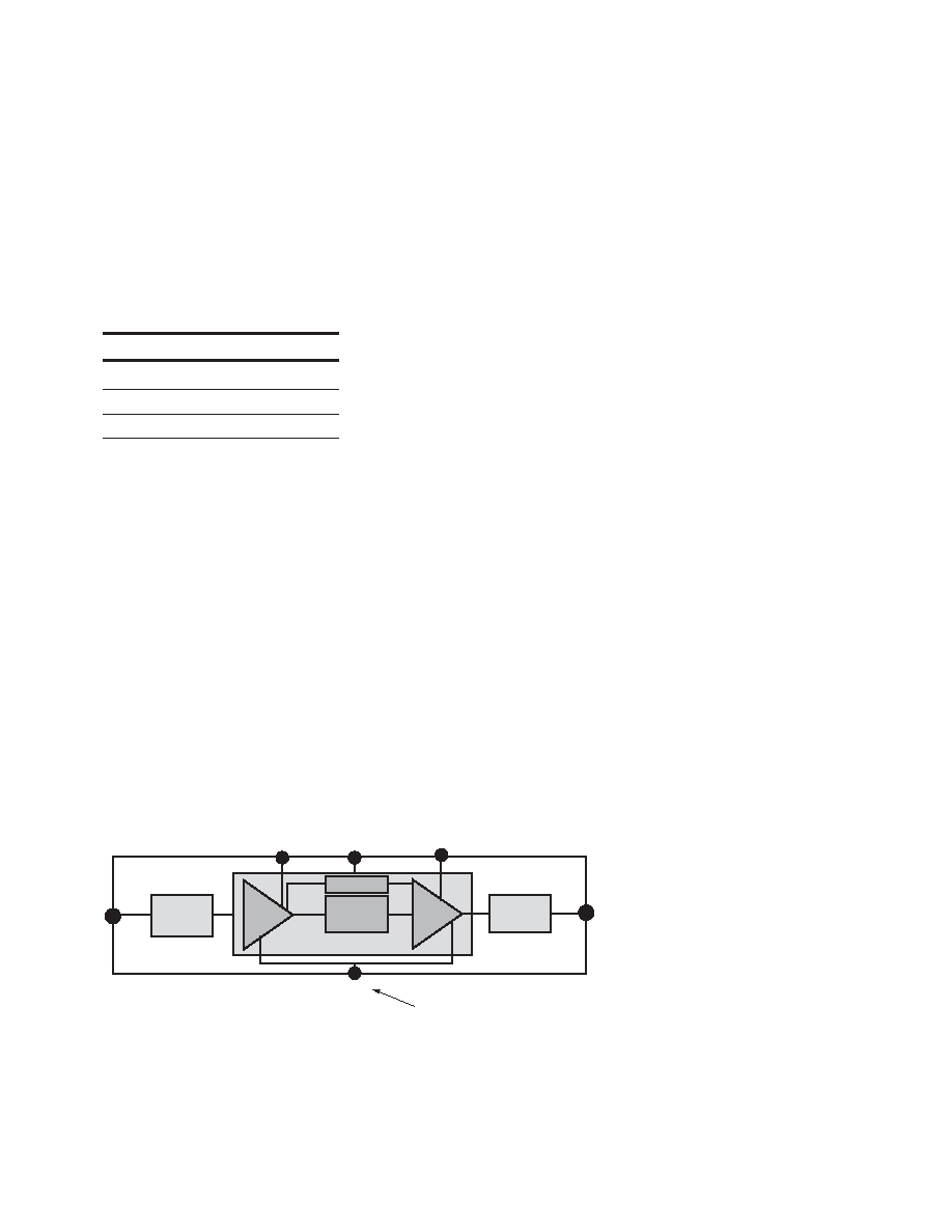
2) Circuit Operation
The design of the power module
(PAM) provide bias control via
Vcntl to achieve optimal RF
performance and power control.
The control pin is labeled Vref
(Vcntl). Please refer to Figure 34
for the block diagram of this
PAM.
Typical Operation Conditions
(Vdd1=Vdd2=Vbias = 3.0V)
Parameter
ACPM-7816
Frequency Range
824 – 849 MHz
Output Power
28.5 dBm
Vcntl
2.5 V
3) Maximum Ratings
Vdd
5.0V
Drain Current
1.5A
Vcntl
3V
RF input
10 dBm
Temperature
-30 to 85
°C
Please Note: Avoid Electrostatic Discharge
on all I/O’s.
4) Heat Sinking
The demonstration PC Board
provides an adequate heat sink.
Maximum device dissipation
should be kept below 2.5 Watts.
5) Testing
- Signal Source
The CDMA modulated signal for
the test is generated using an
Agilent ESG-D4000A (or ESG-
D3000A) Digital Signal Generator
with the following settings:
CDMA Setup : Reverse
Spreading: On
Bits/Symbol: 1
Data: PN15
Modulation: OQPSK
Chip Rate: 1.2288 Mcps
High Crest: On
Filter: Std
Phase Polarity: Invert
- ACPR Measurement
The ACPR (and channel power) is
measured using an Agilent 4406
VSA with corresponding ACPR
offsets for IS-98c and JSTD-8.
Averaging of 10 is used for ACPR
measurements.
- DC Connection
A DC Connector is provided to
allow ease of connection to the
I/O’s. Wires can be soldered to
the connector pins, or the
connector can be removed and
I/O’s contacted via clip leads or
direct soldered connections. The
wiring of I/O’s are listed in
Figure 1 through 3 and Pin
configuration table. The Vdd
sense connections are provided
to allow the use of remote-
sensing power supplies for
compensation of PCB traces and
cable resistance.
- Device Operation
1) Connect RF Input and Output
for the band under test.
2) Terminate all unused RF
ports into 50 Ohms.
3) Connect Vdd1 and Vdd2
supplies (including remote
sensing labeled Vdd1 S and
Vdd2 S on the board). Nomi-
nal voltage is 3.4V.
4) Connect Vcntl supply and set
reference voltage to the
voltage shown in the data
packet. Note that the Vcntl pin
is on the back side of the
demonstration board. Please
limit Vcntl to not exceed the
corresponding listed “DC
Biasing Condition” in the Data
Packet. Note that increasing
Vcntl over the corresponding
listed “DC Biasing Condition”
can result in power decrease
and current can exceed the
rated limit.
5) Apply RF input power accord-
ing to the values listed in
“Operation Data” in Data
Packet.
6) Power down in opposite
sequence.
Figure 34. Power Module Block Diagram.
Input
Vdd1
Passive
Input
Match
On Chip
Inter-stage
Match
Bias Circuit
Passive
Output
Match
Vdd2
Output
Vcntl
Single control bias setting for low Idq
and 40% PAE at Pout = 28.5 dBm
Vbias
相关PDF资料 |
PDF描述 |
|---|---|
| ACPM-7816-TR1 | 824 MHz - 849 MHz RF/MICROWAVE NARROW BAND LOW POWER AMPLIFIER |
| ACPM-7821-BLK | 898 MHz - 925 MHz RF/MICROWAVE NARROW BAND MEDIUM POWER AMPLIFIER |
| ACPM-7822-BLK | 898 MHz - 925 MHz RF/MICROWAVE NARROW BAND LOW POWER AMPLIFIER |
| ACPM-7822-TR1 | 898 MHz - 925 MHz RF/MICROWAVE NARROW BAND LOW POWER AMPLIFIER |
| ACPM-7833-BLK | 1850 MHz - 1910 MHz RF/MICROWAVE NARROW BAND MEDIUM POWER AMPLIFIER |
相关代理商/技术参数 |
参数描述 |
|---|---|
| ACPM-7821 | 制造商:AVAGO 制造商全称:AVAGO TECHNOLOGIES LIMITED 功能描述:4 x 4 Power Amplifier Module for J-CDMA (898 - 925 MHz) |
| ACPM-7821-BLK | 制造商:AVAGO 制造商全称:AVAGO TECHNOLOGIES LIMITED 功能描述:4 x 4 Power Amplifier Module for J-CDMA (898 - 925 MHz) |
| ACPM-7821-TR1 | 制造商:AVAGO 制造商全称:AVAGO TECHNOLOGIES LIMITED 功能描述:4 x 4 Power Amplifier Module for J-CDMA (898 - 925 MHz) |
| ACPM-7822 | 制造商:AVAGO 制造商全称:AVAGO TECHNOLOGIES LIMITED 功能描述:JCDMA 4x4 Power Amplifier Module (898-925MHz) |
| ACPM-7822-BLK | 制造商:AVAGO 制造商全称:AVAGO TECHNOLOGIES LIMITED 功能描述:JCDMA 4x4 Power Amplifier Module (898-925MHz) |
发布紧急采购,3分钟左右您将得到回复。