- 您现在的位置:买卖IC网 > PDF目录10803 > AD421BRRL (Analog Devices Inc)IC DAC SNGL 16BIT 16-SOIC T/R PDF资料下载
参数资料
| 型号: | AD421BRRL |
| 厂商: | Analog Devices Inc |
| 文件页数: | 3/14页 |
| 文件大小: | 0K |
| 描述: | IC DAC SNGL 16BIT 16-SOIC T/R |
| 产品培训模块: | Data Converter Fundamentals DAC Architectures |
| 产品变化通告: | Product Discontinuance 27/Oct/2011 |
| 标准包装: | 1,000 |
| 设置时间: | 8ms |
| 位数: | 16 |
| 数据接口: | 串行 |
| 转换器数目: | 1 |
| 电压电源: | 单电源 |
| 功率耗散(最大): | 450mW |
| 工作温度: | -40°C ~ 85°C |
| 安装类型: | 表面贴装 |
| 封装/外壳: | 16-SOIC(0.295",7.50mm 宽) |
| 供应商设备封装: | 16-SOIC W |
| 包装: | 带卷 (TR) |
| 输出数目和类型: | 1 电流,单极 |
AD421
–11–
REV. C
DVDD AVDD
REF IN
CS
DATA OUT
SCLK
DATA IN
AGND
DGND
MCLK IN
MCLK OUT
AD7714/
AD7715
ANALOG
TO
DIGITAL
CONVERTER
SENSORS
RTD
mV
TC
4.7 F
REF OUT1
BOOST
VCC
LV
COMP
DRIVE
LOOP
RTN
REF OUT2
REF IN
CLOCK
LATCH
DATA
COM
C1
C2
C3
LOOP
POWER
0.01 F
DN25D
2.2 F
3.3V
1.25V
4.7 F
AMBIENT
TEMP
SENSOR
AD421
MICROCONTROLLER
VCC
GND
0.01 F
1k
1000pF
0.1 F
100k
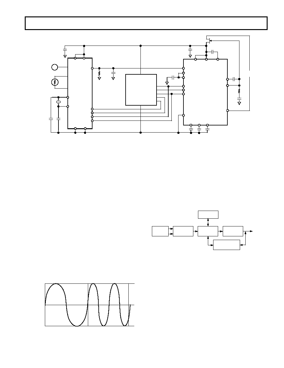
Figure 14. AD421 in Smart Transmitter Application
Figure 16 shows a block diagram of a smart and intelligent
transmitter. An intelligent transmitter is a transmitter in which
the functions of the microprocessor are shared between deriving
the primary measurement signal, storing information regarding
the transmitter itself, its application data and its location and
also managing a communication system which enables two way
communication to be superimposed on the same circuit that
carries the measurement signal. A smart transmitter incorporat-
ing the HART protocol is an example of a smart intelligent
transmitter.
4mA TO 20mA
MEASUREMENT
CIRCUIT
MICRO-
PROCESSOR
D/A
CONVERTER
A/D
CONVERTER
MEMORY
SENSORS
COMMUNICATION
SYSTEM
Figure 16. Smart and Intelligent Transmitter
Figure 17 shows an example of the AD421 in a HART transmit-
ter application. Most of the circuit is as outlined in the smart
transmitter as shown in Figure 14. The HART data transmitted
on the loop is received by the transmitter using a bandpass filter
and modem and the HART data is transferred to the micro-
controller’s UART or asynchronous serial port. HART data to
be transmitted on the loop is sent from the microcontroller’s
UART or asynchronous serial port to the modem. It is then
waveshaped before being coupled onto the AD421’s output at
the C3 pin. The value of the coupling capacitor CC is determined
by the waveshaper output and the C3 capacitor of the AD421. The
blocks containing the Bell 202 Modem, waveshaper and bandpass
filter come in a complete solution with the 20C15 from Symbios
Logic, Inc., or HT2012 from SMAR Research Corp.
For a more complete AD421-20C15 interface, please refer to
Application Note AN-534 on the Analog Devices’ website
www.analog.com or contact your local sales office.
HART Interfacing
The HART protocol uses a frequency shift (FSK) keying tech-
nique based on the Bell 202 Communication Standard which is
one of several standards used to transmit digital signals over
the telephone lines. This technique is used to superimpose
digital communication on to the 4 mA to 20 mA current loop
connecting the central system to the transmitter in the field.
Two different frequencies, 1200 Hz and 2200 Hz, are used to
represent binary 1 and 0 respectively, as shown in Figure 15.
These sine wave tones are superimposed on the dc signal at a
low level with the average value of the sine wave signal being
zero. This allows simultaneous analog and digital communica-
tions. Additionally, no dc component is added to the existing
4 mA to 20 mA signal regardless of the digital data being sent
over the line. Consequently, existing analog instruments con-
tinue to work in systems that implement HART as the low-pass
filtering usually present effectively removes the digital signal. A
single pole 10 Hz low-pass filter effectively reduces the commu-
nication signal to a ripple of about
± 0.01% of the full-scale
signal. The HART protocol specifies that master devices like a
host control system or a hand held terminal transmit a voltage
signal whereas a slave or field device transmits a current signal.
The current signal is converted into a corresponding voltage by
the loop load resistor.
APPROX
+0.5mA
APPROX
–0.5mA
1200Hz
“1”
2200Hz
“0”
Figure 15. HART Transmission of Digital Signals
相关PDF资料 |
PDF描述 |
|---|---|
| DAC8800FP | IC DAC 8BIT OCTAL CMOS 20-DIP |
| AD5320BRM-REEL7 | IC DAC 12BIT R-R W/BUFF 8-MSOP |
| AD5320BRM-REEL | IC DAC 12BIT R-R W/BUFF 8-MSOP |
| BU7231G-TR | IC COMPARATOR SGL 5.5V SSOP-5 |
| AD5318BRU-REEL7 | IC DAC 10BIT OCTAL BUFF 16-TSSOP |
相关代理商/技术参数 |
参数描述 |
|---|---|
| AD421BRRL7 | 功能描述:IC DAC SNGL 16BIT 16-SOIC T/R RoHS:否 类别:集成电路 (IC) >> 数据采集 - 数模转换器 系列:- 标准包装:47 系列:- 设置时间:2µs 位数:14 数据接口:并联 转换器数目:1 电压电源:单电源 功率耗散(最大):55µW 工作温度:-40°C ~ 85°C 安装类型:表面贴装 封装/外壳:28-SSOP(0.209",5.30mm 宽) 供应商设备封装:28-SSOP 包装:管件 输出数目和类型:1 电流,单极;1 电流,双极 采样率(每秒):* |
| AD421BRURL | 制造商:未知厂家 制造商全称:未知厂家 功能描述:16-Bit Digital-to-Analog Converter |
| AD421BRZ | 功能描述:IC DAC SRL 16BIT 16-SOIC RoHS:是 类别:集成电路 (IC) >> 数据采集 - 数模转换器 系列:- 产品培训模块:Data Converter Fundamentals DAC Architectures 标准包装:750 系列:- 设置时间:7µs 位数:16 数据接口:并联 转换器数目:1 电压电源:双 ± 功率耗散(最大):100mW 工作温度:0°C ~ 70°C 安装类型:表面贴装 封装/外壳:28-LCC(J 形引线) 供应商设备封装:28-PLCC(11.51x11.51) 包装:带卷 (TR) 输出数目和类型:1 电压,单极;1 电压,双极 采样率(每秒):143k |
| AD421BRZRL | 功能描述:IC DAC 16BIT LOOP 4-20MA 16SOIC RoHS:是 类别:集成电路 (IC) >> 数据采集 - 数模转换器 系列:- 标准包装:47 系列:- 设置时间:2µs 位数:14 数据接口:并联 转换器数目:1 电压电源:单电源 功率耗散(最大):55µW 工作温度:-40°C ~ 85°C 安装类型:表面贴装 封装/外壳:28-SSOP(0.209",5.30mm 宽) 供应商设备封装:28-SSOP 包装:管件 输出数目和类型:1 电流,单极;1 电流,双极 采样率(每秒):* |
| AD421BRZRL7 | 功能描述:IC DAC 16BIT LOOP 4-20MA 16SOIC RoHS:是 类别:集成电路 (IC) >> 数据采集 - 数模转换器 系列:- 产品培训模块:Lead (SnPb) Finish for COTS Obsolescence Mitigation Program 标准包装:50 系列:- 设置时间:4µs 位数:12 数据接口:串行 转换器数目:2 电压电源:单电源 功率耗散(最大):- 工作温度:-40°C ~ 85°C 安装类型:表面贴装 封装/外壳:8-TSSOP,8-MSOP(0.118",3.00mm 宽) 供应商设备封装:8-uMAX 包装:管件 输出数目和类型:2 电压,单极 采样率(每秒):* 产品目录页面:1398 (CN2011-ZH PDF) |
发布紧急采购,3分钟左右您将得到回复。