- 您现在的位置:买卖IC网 > PDF目录373871 > AD5222 (Analog Devices, Inc.) Increment/Decrement Dual Digital Potentiometer PDF资料下载
参数资料
| 型号: | AD5222 |
| 厂商: | Analog Devices, Inc. |
| 元件分类: | 数字电位计 |
| 英文描述: | Increment/Decrement Dual Digital Potentiometer |
| 中文描述: | 递增/递减双数字电位器 |
| 文件页数: | 8/10页 |
| 文件大小: | 173K |
| 代理商: | AD5222 |
AD5222
–8–
REV. 0
OPERATION
The AD5222 provides a 128-position, digitally-controlled, variable
resistor (VR) device. Changing the VR settings is accomplished
by pulsing the CLK pin while
CS
is active low. The U/
D
(UP/
DOWN) control input pin controls the direction of the increment.
When the wiper hits the end of the resistor (Terminal A or B)
additional CLK pulses no longer change the wiper setting. The
wiper position is immediately decoded by the wiper decode logic
changing the wiper resistance. Appropriate debounce circuitry is
required when push-button switches are used to control the
count sequence and direction of count. The exact timing require-
ments are shown in Figure 2. The AD5222 powers ON in a
centered wiper position, exhibiting nearly equal resistances of
R
WA
and R
WB
.
DECODE
UP/DOWN
COUNTER
AD5222
V
SS
A1
W1
B1
DECODE
UP/DOWN
COUNTER
A2
W2
B2
POR
DAC
SELECT
AND
ENABLE
CLK
CS
U/
D
DACSEL
MODE
GND
V
DD
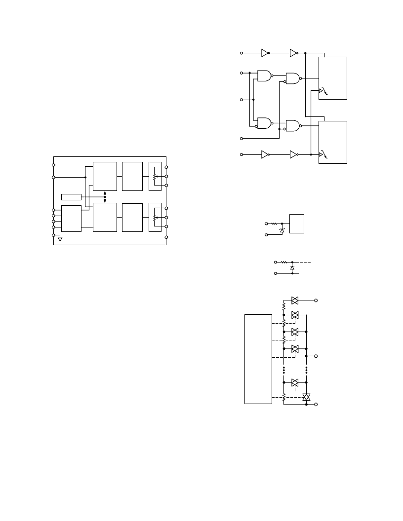
Figure 29. Block Diagram
DIGITAL INTERFACING OPERATION
The AD5222 contains a push-button controllable interface. The
active inputs are clock (CLK),
CS
and up/down (U/
D
). While
the MODE, and DACSEL pins control common updates or
individual updates. The negative-edge sensitive CLK input
requires clean transitions to avoid clocking multiple pulses into
the internal UP/DOWN counter register, Figure 30. Standard
logic families work well. If mechanical switches are used for
product evaluation a flip-flop or other suitable means should
debounce them. When
CS
is taken active low, the clock begins
to increment or decrement the internal up/down counter, depen-
dent upon the state of the U/
D
control pin. The UP/DOWN
counter value (D) starts at 40
H
at system power ON. Each new
CLK pulse will increment the value of the internal counter by
1 LSB until the full-scale value of 7F
H
is reached, as long as the
U/
D
pin is logic high. If the U/
D
pin is taken to logic low, the
counter will count down, stopping at code 00
H
(zero-scale).
Additional clock pulses on the CLK pin are ignored when the
wiper is at either the 00
H
position or the 7F
H
position. The
detailed digital logic interface circuitry is shown in Figure 30.
RDAC 1
U/
D
COUNTER
RDAC 2
U/
D
COUNTER
CLK
CS
U/
D
DACSEL
MODE
Figure 30. Detailed Digital Logic Interface Circuit
All digital inputs (
CS
, U/
D
, CLK, MODE, DACSEL) are
protected with a series input resistor and parallel Zener ESD
structure shown in Figure 31. All potentiometer terminal pins
(A, B, W) are protected from ESD as shown in Figure 32.
LOGIC
1k
V
V
SS
Figure 31. Equivalent ESD Protection Digital Pins
20
V
A, B, W
V
SS
Figure 32. Equivalent ESD Protection Analog Pins
D0
D1
D2
D3
D4
D5
D6
RDAC
UP/DOWN
CNTR
&
DECODE
W
B
R
S
= R
NOMINAL
/128
R
S
R
S
R
S
A
R
S
Figure 33. AD5222 Equivalent RDAC Circuit
相关PDF资料 |
PDF描述 |
|---|---|
| AD5222BR10 | Increment/Decrement Dual Digital Potentiometer |
| AD5222BR100 | Increment/Decrement Dual Digital Potentiometer |
| AD5222BR50 | Increment/Decrement Dual Digital Potentiometer |
| AD5222BRU10 | Increment/Decrement Dual Digital Potentiometer |
| AD5222BRU100 | Increment/Decrement Dual Digital Potentiometer |
相关代理商/技术参数 |
参数描述 |
|---|---|
| AD5222BR10 | 制造商:Analog Devices 功能描述:Digital Potentiometer 128POS 10KOhm Dual 14-Pin SOIC N 制造商:Rochester Electronics LLC 功能描述:7-BIT RDAC WITH UP/DWN CONTROL - Bulk |
| AD5222BR100 | 制造商:Analog Devices 功能描述:Digital Potentiometer 128POS 100KOhm Dual 14-Pin SOIC N 制造商:Rochester Electronics LLC 功能描述:7-BIT RDAC WITH UP/DWN CONTROL - Bulk |
| AD5222BR100-REEL7 | 制造商:Analog Devices 功能描述:Digital Potentiometer 128POS 100KOhm Dual 14-Pin SOIC N T/R |
| AD5222BR10-REEL7 | 制造商:Analog Devices 功能描述:Digital Potentiometer 128POS 10KOhm Dual 14-Pin SOIC N T/R 制造商:Rochester Electronics LLC 功能描述:7-BIT RDAC WITH UP/DWN CONTROL - Tape and Reel |
| AD5222BR1M | 制造商:Analog Devices 功能描述:Digital Potentiometer 128POS 1MOhm Dual 14-Pin SOIC N 制造商:Rochester Electronics LLC 功能描述:7-BIT RDAC WITH UP/DWN CONTROL - Bulk |
发布紧急采购,3分钟左右您将得到回复。