- 您现在的位置:买卖IC网 > PDF目录8582 > AD5544ARSZ-REEL7 (Analog Devices Inc)IC DAC 16BIT QUAD SRL 28SSOP PDF资料下载
参数资料
| 型号: | AD5544ARSZ-REEL7 |
| 厂商: | Analog Devices Inc |
| 文件页数: | 7/24页 |
| 文件大小: | 0K |
| 描述: | IC DAC 16BIT QUAD SRL 28SSOP |
| 标准包装: | 500 |
| 设置时间: | 900ns |
| 位数: | 16 |
| 数据接口: | 串行,SPI? |
| 转换器数目: | 4 |
| 电压电源: | 双 ± |
| 功率耗散(最大): | 1.25mW |
| 工作温度: | -40°C ~ 125°C |
| 安装类型: | 表面贴装 |
| 封装/外壳: | 28-SSOP(0.209",5.30mm 宽) |
| 供应商设备封装: | 28-SSOP |
| 包装: | 带卷 (TR) |
| 输出数目和类型: | 4 电流,单极;4 电流,双极 |
Data Sheet
AD5544/AD5554
Rev. G | Page 15 of 24
SERIAL DATA INTERFACE
The AD5544/AD5554 use a 3-wire (CS, SDI, CLK), SPI-compatible
serial data interface. Serial data of the AD5544/AD5554 is clocked
into the serial input register in an 18-bit and 16-bit data-word
format, respectively. The MSB bits are loaded first. Table 5 defines
the 18 data-word bits for the AD5544, and Table 6 defines the
16 data-word bits for the AD5554. Data is placed on the SDI pin
and clocked into the register on the positive clock edge of CLK,
subject to the data setup and data hold time requirements specified
in the interface timing specifications (see Table 1 and Table 2).
Data can be clocked in only while the CS chip select pin is active
low. For the AD5544, only the last 18 bits clocked into the serial
register are interrogated when the CS pin returns to the logic high
state; extra data bits are ignored. For the AD5554, only the last
16 bits clocked into the serial register are interrogated when the
CS pin returns to the logic high state. Because most microcon-
trollers output serial data in 8-bit bytes, three right-justified data
bytes can be written to the AD5544. Keeping the CS line low
between the first, second, and third byte transfers results in a
successful serial register update.
Similarly, two right-justified data bytes can be written to the
AD5554. Keeping the CS line low between the first and second
byte transfer results in a successful serial register update.
When the data is properly aligned in the shift register, the posi-
tive edge of the CS initiates the transfer of new data to the target
DAC register, determined by the decoding of Address Bit A1
and Figure 3 define the characteristics of the software serial
interface.
the characteristics of the software serial interface. Figure 23 and
Figure 24 show the equivalent logic interface for the key digital
control pins for the AD5544. The AD5554 has a similar configu-
ration, except that it has 14 data bits. Two additional pins, RS and
MSB, provide hardware control over the preset function and
DAC register loading. If these functions are not needed, the RS
pin can be tied to logic high. The asynchronous input RS pin
forces all input and the DAC registers to either the zero-code
state (MSB = 0) or the half-scale state (MSB = 1).
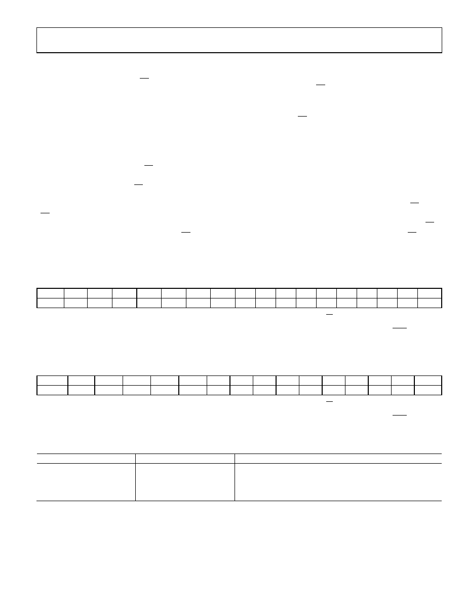
Table 5. AD5544 Serial Input Register Data Format (Data Is Loaded in the MSB-First Format)1
MSB
LSB
B17
B16
B15
B14
B13
B12
B11
B10
B9
B8
B7
B6
B5
B4
B3
B2
B1
B0
A1
A0
D15
D14
D13
D12
D11
D10
D9
D8
D7
D6
D5
D4
D3
D2
D1
D0
1
Only the last 18 bits of data clocked into the serial register (address + data) are inspected when the positive edge of the CS line returns to logic high. At this point, an
internally generated load strobe transfers the serial register data contents (Bit D15 to Bit D0) to the decoded DAC input register address determined by Bit A1 and Bit A0.
Any extra bits clocked into the AD5544 shift register are ignored; only the last 18 bits clocked in are used. If double-buffered data is not needed, the LDAC pin can be
tied logic low to disable the DAC registers.
Table 6. AD5554 Serial Input Register Data Format (Data Is Loaded in the MSB-First Format)1
MSB
LSB
B15
B14
B13
B12
B11
B10
B9
B8
B7
B6
B5
B4
B3
B2
B1
B0
A1
A0
D13
D12
D11
D10
D9
D8
D7
D6
D5
D4
D3
D2
D1
D0
1
Only the last 16 bits of data clocked into the serial register (address + data) are inspected when the positive edge of the CS line returns to logic high. At this point, an
internally generated load strobe transfers the serial register data contents (Bit D13 to Bit D0) to the decoded DAC input register address determined by Bit A1 and Bit A0.
Any extra bits clocked into the AD5554 shift register are ignored; only the last 16 bits clocked in are used. If double-buffered data is not needed, the LDAC pin can be
tied logic low to disable the DAC registers.
Table 7. Address Decode
A1
A0
DAC Decoded
0
DAC A
0
1
DAC B
1
0
DAC C
1
DAC D
相关PDF资料 |
PDF描述 |
|---|---|
| AD7228ACPZ-REEL | IC DAC 8BIT OCTAL W/AMP 28-PLCC |
| AD7228ACRZ-REEL | IC DAC 8BIT OCTAL W/AMP 24SOIC |
| AD7225KP-REEL | IC DAC 8BIT QUAD W/AMP 28-PLCC |
| AD7245ABN | IC DAC 12BIT W/REF 24-DIP |
| AD5542BR | IC DAC 16BIT SERIAL-IN 14-SOIC |
相关代理商/技术参数 |
参数描述 |
|---|---|
| AD5544BCPZ-R2 | 制造商:Analog Devices 功能描述: |
| AD5544BCPZ-RL7 | 功能描述:IC DAC 16BIT SER QUAD 32-LFCSP RoHS:是 类别:集成电路 (IC) >> 数据采集 - 数模转换器 系列:- 产品培训模块:Data Converter Fundamentals DAC Architectures 标准包装:750 系列:- 设置时间:7µs 位数:16 数据接口:并联 转换器数目:1 电压电源:双 ± 功率耗散(最大):100mW 工作温度:0°C ~ 70°C 安装类型:表面贴装 封装/外壳:28-LCC(J 形引线) 供应商设备封装:28-PLCC(11.51x11.51) 包装:带卷 (TR) 输出数目和类型:1 电压,单极;1 电压,双极 采样率(每秒):143k |
| AD5544BRSZ | 功能描述:IC DAC 16BIT SER QUAD 28SSOP RoHS:是 类别:集成电路 (IC) >> 数据采集 - 数模转换器 系列:- 标准包装:1 系列:- 设置时间:4.5µs 位数:12 数据接口:串行,SPI? 转换器数目:1 电压电源:单电源 功率耗散(最大):- 工作温度:-40°C ~ 125°C 安装类型:表面贴装 封装/外壳:8-SOIC(0.154",3.90mm 宽) 供应商设备封装:8-SOICN 包装:剪切带 (CT) 输出数目和类型:1 电压,单极;1 电压,双极 采样率(每秒):* 其它名称:MCP4921T-E/SNCTMCP4921T-E/SNRCTMCP4921T-E/SNRCT-ND |
| AD5544BRSZ-REEL7 | 功能描述:IC DAC 16BIT QUAD SRL 28SSOP RoHS:是 类别:集成电路 (IC) >> 数据采集 - 数模转换器 系列:- 产品培训模块:Data Converter Fundamentals DAC Architectures 标准包装:750 系列:- 设置时间:7µs 位数:16 数据接口:并联 转换器数目:1 电压电源:双 ± 功率耗散(最大):100mW 工作温度:0°C ~ 70°C 安装类型:表面贴装 封装/外壳:28-LCC(J 形引线) 供应商设备封装:28-PLCC(11.51x11.51) 包装:带卷 (TR) 输出数目和类型:1 电压,单极;1 电压,双极 采样率(每秒):143k |
| AD5544EVAL | 制造商:AD 制造商全称:Analog Devices 功能描述:Quad, Current-Output, Serial-Input 16-/14-Bit DACs |
发布紧急采购,3分钟左右您将得到回复。