- 您现在的位置:买卖IC网 > PDF目录97394 > AD5PS-1+ (MINI-CIRCUITS) 1 MHz - 400 MHz RF/MICROWAVE COMBINER, 1.8 dB INSERTION LOSS PDF资料下载
参数资料
| 型号: | AD5PS-1+ |
| 厂商: | MINI-CIRCUITS |
| 元件分类: | 分路器/合路器 |
| 英文描述: | 1 MHz - 400 MHz RF/MICROWAVE COMBINER, 1.8 dB INSERTION LOSS |
| 封装: | ROHS COMPLIANT, CASE CJ725, 8 PIN |
| 文件页数: | 1/1页 |
| 文件大小: | 316K |
| 代理商: | AD5PS-1+ |
L = 1-10 MHz
M = 10-200 MHz
U= 200-400 MHz
FREQ.
RANGE
(MHz)
ISOLATION
(dB)
INSERTION LOSS (dB)
ABOVE 7.0 dB
PHASE
UNBALANCE
(Degrees)
AMPLITUDE
UNBALANCE
(dB)
f
L-fU
L
M
U
L
M
U
L
M
U
L
M
U
Typ. Min Typ. Min Typ. Min Typ. Max. Typ. Max. Typ. Max.
Max.
1-400
35
18
25
20
27
20
0.15
0.5
0.3
1.0
0.8
1.8
1
6
9
0.3
0.4
0.6
ISO 9001 ISO 14001 AS 9100 CERTIFIED
Mini-Circuits
P.O. Box 350166, Brooklyn, New York 11235-0003 (718) 934-4500 Fax (718) 332-4661 The Design Engineers Search Engine
Provides ACTUAL Data Instantly at
Notes: 1. Performance and quality attributes and conditions not expressly stated in this specification sheet are intended to be excluded and do not form a part of this specification sheet. 2. Electrical specifications
and performance data contained herein are based on Mini-Circuit’s applicable established test performance criteria and measurement instructions. 3. The parts covered by this specification sheet are subject to
Mini-Circuits standard limited warranty and terms and conditions (collectively, “Standard Terms”); Purchasers of this part are entitled to the rights and benefits contained therein. For a full statement of the Standard
Terms and the exclusive rights and remedies thereunder, please visit Mini-Circuits’ website at www.minicircuits.com/MCLStore/terms.jsp.
For detailed performance specs
& shopping online see web site
minicircuits.com
IF/RF MICROWAVE COMPONENTS
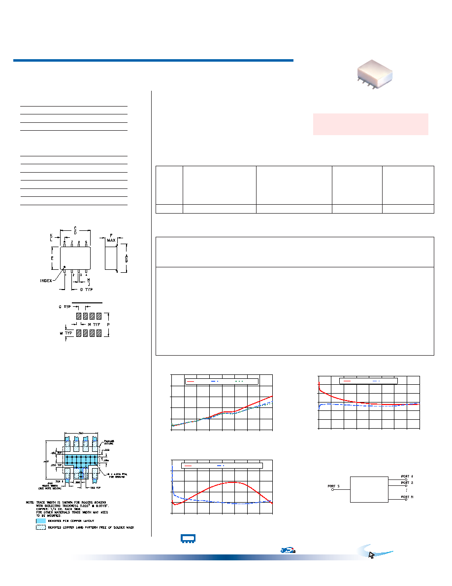
Typical Performance Data
5 Way-0° 50
1 to 400 MHz
Power Splitter/Combiner
Surface Mount
AD5PS-1+
Maximum Ratings
Pin Connections
SUM PORT
1
PORT 1
8
PORT 2
7
PORT 3
6
PORT 4
5
PORT 5
4
GROUND
2,3
Operating Temperature
-40°C to 85°C
Storage Temperature
-55°C to 100°C
Power Input (as a splitter)
0.5W max.
Internal Dissipation
0.4W max.
Outline Drawing
Electrical Specifications
REV. H
M127604
ED-7796/1
AD5PS-1+
HY/TD/CP/AM
100518
AD5PS-1+
TOTAL LOSS
7.0
7.4
7.8
8.2
8.6
9.0
0
50
100
150
200
250
300
350
400
FREQUENCY (MHz)
TO
TA
L
LO
S
(d
B
)
S-1(dB)
S-2(dB)
S-5(dB)
AD5PS-1+
ISOLATION
0
10
20
30
40
50
60
0
50
100
150
200
250
300
350
400
FREQUENCY (MHz)
ISOLATION
(dB)
1-2(dB)
1-3(dB)
AD5PS-1+
VSWR
1.0
1.1
1.2
1.3
1.4
1.5
0
50
100
150
200
250
300
350
400
FREQUENCY (MHz)
V
S
W
R
#S-VSWR
#OUTPUTS-VSWR
PCB Land Pattern
Suggested Layout,
Tolerance to be within ±.002
electrical schematic
A
B
C
D
E
F
G
.345
.400
.385
.435
.310
.215
.100
8.76 10.16
9.78 11.05
7.87
5.46
2.54
H
J
K
L
M
N
P
wt
.015
.025
.035
.075
.120
.060
.420 grams
0.38
0.64
0.89
1.91
3.05
1.52 10.67
0.45
Features
wideband,1to400MHz
highisolation,27dBtyp.
goodinputportmatchingVSWR,1.22typ.
goodoutputportmatchingVSWR,1.12typ.
smallsurfacemountpackage
Applications
VHF-TV
aircraftcommunications
CASE STYLE: CJ725
PRICE: $19.95 ea. QTY. (10-49)
Demo Board MCL P/N: TB-82
Suggested PCB Layout (PL-088)
Freq.
(MHz)
Total Loss1
(dB)
Amp.
Unbal.
(dB)
Isolation
(dB)
Phase
Unbal.
(deg.)
VSWR
S
VSWR
OUTPUTS
S-1
S-2
S-3
S-4
S-5
1-2
1-3
2-3
3-5
4-5
Outline Dimensions (
)
inch
mm
1.00
7.22
7.21
7.23
7.21
7.23
0.02
53.10
21.98
39.65
21.51 33.16
0.22
1.12
1.45
2.80
7.18
7.16
7.15
7.16
0.03
45.24
25.05
43.27
24.73 38.07
0.13
1.10
1.26
4.60
7.17
7.15
7.14
7.16
7.14
0.03
44.17
26.12
44.25
25.93 40.51
0.26
1.09
1.21
6.40
7.13
7.14
7.16
7.15
0.03
43.48
26.69
44.52
26.55
41.81
0.24
1.09
1.19
8.20
7.16
7.14
7.17
7.16
7.17
0.03
42.90
27.02
44.57
26.94 42.66
0.24
1.09
1.18
10.00
7.15
7.17
7.14
7.16
7.17
0.03
42.60
27.25
44.11
27.17
43.01
0.17
1.08
1.17
40.00
7.21
7.22
7.19
7.21
0.03
38.08
27.77
38.44
27.75
37.68
0.85
1.10
1.14
70.00
7.28
7.29
7.28
0.01
34.66
27.46
34.77
27.36 33.71
1.42
1.14
1.13
100.00
7.32
7.30
7.31
7.32
0.02
32.37
26.97
32.32
26.77
31.14
2.12
1.18
1.12
125.00
7.41
7.40
7.41
0.02
30.92
26.57
30.86
26.33 29.64
2.27
1.21
1.12
150.00
7.46
7.42
7.40
7.41
7.44
0.07
29.80
26.19
29.75
25.89 28.46
2.89
1.24
1.11
200.00
7.64
7.59
7.56
7.55
7.59
0.09
28.24
25.57
28.17
25.17
26.79
3.75
1.28
1.10
250.00
7.67
7.60
7.54
7.55
7.59
0.12
27.51
25.39
27.46
24.88 25.94
4.46
1.29
1.09
300.00
7.86
7.74
7.69
7.74
0.18
27.29
25.61
27.29
25.03 25.56
5.14
1.26
1.09
400.00
8.23
8.03
7.90
7.88
7.97
0.34
27.54
29.08
27.87
27.64 25.67
6.12
1.09
1.12
Permanentdamagemayoccurifanyoftheselimitsareexceeded.
+ RoHS compliant in accordance
with EU Directive (2002/95/EC)
The +Suffix has been added in order to identify RoHS
Compliance. See our web site for RoHS Compliance
methodologies and qualifications.
1.TotalLoss=InsertionLoss+7dBsplitterloss.
相关PDF资料 |
PDF描述 |
|---|---|
| ADC-16-4-75 | 5 MHz - 1000 MHz RF/MICROWAVE DIRECTIONAL COUPLER, 1.2 dB INSERTION LOSS-MAX |
| ADC-16-4-75+ | 5 MHz - 1000 MHz RF/MICROWAVE DIRECTIONAL COUPLER, 1.2 dB INSERTION LOSS-MAX |
| ADC-ED10228/1+ | 5 MHz - 1000 MHz RF/MICROWAVE DIRECTIONAL COUPLER, 0.7 dB INSERTION LOSS-MAX |
| ADE-1ASK | 2 MHz - 600 MHz RF/MICROWAVE DOUBLE BALANCED MIXER, 7.5 dB CONVERSION LOSS-MAX |
| ADE-1ASK+ | 2 MHz - 600 MHz RF/MICROWAVE DOUBLE BALANCED MIXER, 7.5 dB CONVERSION LOSS-MAX |
相关代理商/技术参数 |
参数描述 |
|---|---|
| AD5T | 制造商:Opto 22 功能描述:I/O Module; 5 VDC @ 170 mA; 0 to degC; UL, CSA, CE Certified 制造商:Opto 22 功能描述:I/O MODULE 制造商:Opto 22 功能描述:I/O MODULE; Leaded Process Compatible:No; Peak Reflow Compatible (260 C):No; No. of Analog Inputs:1; No. of Digital Outputs:1; No. of Outputs:1; Resolution:12 Bits; Signal Input Type:J Thermocouple ;RoHS Compliant: No 制造商:Opto 22 功能描述:Access Module Analog J Thermocouple Input Isolated Ad5T |
| AD6 | 功能描述:保险丝 6A 415V AC / 250V DC RoHS:否 制造商:Littelfuse 产品:Surface Mount Fuses 电流额定值:0.5 A 电压额定值:600 V 保险丝类型:Fast Acting 保险丝大小/组:Nano 尺寸:12.1 mm L x 4.5 mm W 安装风格: 端接类型:SMD/SMT 系列:485 |
| AD60 | 制造商:未知厂家 制造商全称:未知厂家 功能描述:CPRIIRNCTEUDI TCI RICMUPITR BIMOA??RD |
| AD60/001-0R2 | 制造商:Analog Devices 功能描述: |
| ad60/001-0reel7 | 制造商:Analog Devices 功能描述: |
发布紧急采购,3分钟左右您将得到回复。