参数资料
| 型号: | AD737-EVALZ |
| 厂商: | Analog Devices Inc |
| 文件页数: | 13/24页 |
| 文件大小: | 0K |
| 描述: | BOARD EVALUATION FOR AD737 |
| 标准包装: | 1 |
| 主要目的: | 接口,RMS 到 DC 转换器 |
| 已用 IC / 零件: | AD737 |
| 已供物品: | 板 |
| 相关产品: | AD737JRZ-RL-ND - IC CONV TRUE RMS-DC LP 8SOIC AD737ARZ-ND - IC TRUE RMS/DC CONV LP 8SOIC AD737ANZ-ND - IC TRUE RMS/DC CONV LP 8-DIP AD737JRZ-5-ND - IC TRUE RMS/DC CONV LP 8-SOIC AD737JRZ-R7-ND - IC TRUE RMS/DC CONV LP 8-SOIC AD737JRZ-5-R7-ND - IC TRUE RMS/DC CONV LP 8-SOIC AD737JRZ-5-RL-ND - IC TRUE RMS/DC CONV LP 8-SOIC AD737JRZ-ND - IC TRUE RMS/DC CONV LP 8-SOIC AD737JNZ-ND - IC TRUE RMS/DC CONV LP 8-DIP AD737KR-REEL7-ND - IC AC RMS TO DC CONV 5V 8-SOIC 更多... |
�� �
�
�Data� Sheet�
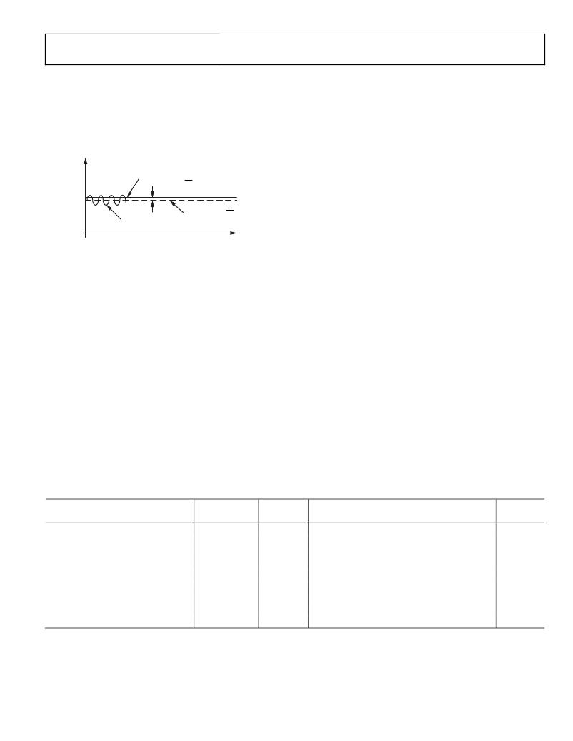
�DC� ERROR,� OUTPUT� RIPPLE,� AND�
�AVERAGING� ERROR�
��a� sine� wave� input� voltage� applied.� As� with� all� real-world� devices,�
�the� ideal� output� of� V� OUT� =� V� IN� is� never� exactly� achieved;� instead,�
�the� output� contains� both� a� dc� and� an� ac� error� component.�
�E� O�
�IDEAL�
�E� O�
�DC� ERROR� =� E� O� –� E� O� (IDEAL)�
�AD737�
�AC� MEASUREMENT� ACCURACY� AND�
�CREST� FACTOR�
�The� crest� factor� of� the� input� waveform� is� often� overlooked� when�
�determining� the� accuracy� of� an� ac� measurement.� Crest� factor� is�
�defined� as� the� ratio� of� the� peak� signal� amplitude� to� the� rms�
�amplitude� (crest� factor� =� V� PEAK� /V� rms).� Many� common�
�waveforms,� such� as� sine� and� triangle� waves,� have� relatively� low�
�crest� factors� (≥2).� Other� waveforms,� such� as� low� duty� cycle�
�pulse� trains� and� SCR� waveforms,� have� high� crest� factors.� These�
�types� of� waveforms� require� a� long� averaging� time� constant� to�
��DOUBLE-FREQUENCY�
�RIPPLE�
�AVERAGE� E� O� =� E� O�
�TIME�
�shows� the� additional� error� vs.� the� crest� factor� of� the� AD737� for�
�various� values� of� C� AV� .�
�CALCULATING� SETTLING� TIME�
�Figure� 24.� Output� Waveform� for� Sine� Wave� Input� Voltage�
�As� shown,� the� dc� error� is� the� difference� between� the� average�
�of� the� output� signal� (when� all� the� ripple� in� the� output� has� been�
�removed� by� external� filtering)� and� the� ideal� dc� output.� The� dc�
�error� component� is,� therefore,� set� solely� by� the� value� of� the�
�averaging� capacitor� used—no� amount� of� post� filtering� (using� a�
�very� large� postfiltering� capacitor,� C� F� )� allows� the� output� voltage�
�to� equal� its� ideal� value.� The� ac� error� component,� an� output�
�ripple,� can� be� easily� removed� using� a� large� enough� C� F� .�
�In� most� cases,� the� combined� magnitudes� of� the� dc� and� ac� error�
�components� must� be� considered� when� selecting� appropriate�
�values� for� C� AV� and� C� F� capacitors.� This� combined� error,� repre-�
�senting� the� maximum� uncertainty� of� the� measurement,� is� termed�
�the� averaging� error� and� is� equal� to� the� peak� value� of� the� output�
�ripple� plus� the� dc� error.� As� the� input� frequency� increases,� both�
�error� components� decrease� rapidly.� If� the� input� frequency�
�doubles,� the� dc� error� and� ripple� reduce� to� one-quarter� and�
�one-half� of� their� original� values,� respectively,� and� rapidly�
�become� insignificant.�
��for� the� AD737� to� settle� when� its� input� level� is� reduced� in� ampli-�
�tude.� The� net� time� required� for� the� rms� converter� to� settle� is�
�the� difference� between� two� times� extracted� from� the� graph:�
�the� initial� time� minus� the� final� settling� time.� As� an� example,�
�consider� the� following� conditions:� a� 33� μF� averaging� capacitor,�
�an� initial� rms� input� level� of� 100� mV,� and� a� final� (reduced)� input�
�level� of� 1� mV.� From� Figure� 17,� the� initial� settling� time� (where�
�the� 100� mV� line� intersects� the� 33� μF� line)� is� approximately�
�80� ms.� The� settling� time� corresponding� to� the� new� or� final�
�input� level� of� 1� mV� is� approximately� 8� seconds.� Therefore,� the�
�net� time� for� the� circuit� to� settle� to� its� new� value� is� 8� seconds�
�minus� 80� ms,� which� is� 7.92� seconds.�
�Note� that,� because� of� the� inherent� smoothness� of� the� decay�
�characteristic� of� a� capacitor/diode� combination,� this� is� the�
�total� settling� time� to� the� final� value� (not� the� settling� time� to� 1%,�
�0.1%,� and� so� on,� of� the� final� value).� Also,� this� graph� provides�
�the� worst-case� settling� time� because� the� AD737� settles� very�
�quickly� with� increasing� input� levels.�
�Table� 5.� Error� Introduced� by� an� Average� Responding� Circuit� When� Measuring� Common� Waveforms�
�Type� of� Waveform�
�Crest� Factor�
�True� RMS�
�Reading� of� an� Average� Responding� Circuit�
�1� V� Peak� Amplitude�
�Undistorted� Sine� Wave�
�Symmetrical� Square� Wave�
�Undistorted� Triangle� Wave�
�Gaussian� Noise� (98%� of� Peaks� <1� V)�
�Rectangular�
�Pulse� Train�
�(V� PEAK� /V� rms)�
�1.414�
�1.00�
�1.73�
�3�
�2�
�10�
�Value� (V)�
�0.707�
�1.00�
�0.577�
�0.333�
�0.5�
�0.1�
�Calibrated� to� an� RMS� Sine� Wave� Value� (V)�
�0.707�
�1.11�
�0.555�
�0.295�
�0.278�
�0.011�
�Error� (%)�
�0�
�11.0�
�?3.8�
�?11.4�
�?44�
�?89�
�SCR� Waveforms�
�50%� Duty� Cycle�
�25%� Duty� Cycle�
�2�
�4.7�
�0.495�
�0.212�
�0.354�
�0.150�
�?28�
�?30�
�Rev.� I� |� Page� 13� of� 24�
�相关PDF资料 |
PDF描述 |
|---|---|
| AD8007AKS-EBZ | BOARD EVAL FOR AD8007AKS |
| AD8018ARU-EVAL | BOARD EVAL FOR AD8018 |
| AD8034ART-EBZ | BOARD EVAL FOR AD8034ART |
| AD8040AR-EBZ | BOARD EVAL FOR AD8040AR |
| AD8045ARD-EBZ | BOARD EVAL FOR AD8045ARD |
相关代理商/技术参数 |
参数描述 |
|---|---|
| AD737JN | 制造商:Analog Devices 功能描述:IC RMS TO DC CONVERTER DIP8 737 |
| AD737JNZ | 功能描述:IC TRUE RMS/DC CONV LP 8-DIP RoHS:是 类别:集成电路 (IC) >> PMIC - RMS 至 DC 转换器 系列:- 标准包装:46 系列:- 电流 - 电源:1.2mA 电源电压:±18 V,36 V 安装类型:表面贴装 封装/外壳:16-SOIC(0.295",7.50mm 宽) 供应商设备封装:16-SOIC W 包装:管件 |
| AD737JR | 制造商:Analog Devices 功能描述:RMS-to-DC Converter 8-Pin SOIC N 制造商:Rochester Electronics LLC 功能描述:RMS-DC CONVERTER IC - Bulk 制造商:Analog Devices 功能描述:Special Function IC Package/Case:8-SOIC |
| AD737JR-5 | 制造商:Analog Devices 功能描述:RMS-to-DC Converter 8-Pin SOIC |
| AD737JR-5-REEL | 功能描述:IC AC RMS TO DC CONV 5V 8-SOIC RoHS:否 类别:集成电路 (IC) >> PMIC - RMS 至 DC 转换器 系列:- 标准包装:46 系列:- 电流 - 电源:1.2mA 电源电压:±18 V,36 V 安装类型:表面贴装 封装/外壳:16-SOIC(0.295",7.50mm 宽) 供应商设备封装:16-SOIC W 包装:管件 |
发布紧急采购,3分钟左右您将得到回复。