参数资料
| 型号: | AD768ARZ-REEL |
| 厂商: | Analog Devices Inc |
| 文件页数: | 8/20页 |
| 文件大小: | 0K |
| 描述: | IC DAC 16BIT 30MSPS 28-SOIC |
| 产品培训模块: | Data Converter Fundamentals DAC Architectures |
| 标准包装: | 1,000 |
| 设置时间: | 25ns |
| 位数: | 16 |
| 数据接口: | 并联 |
| 转换器数目: | 1 |
| 电压电源: | 双 ± |
| 功率耗散(最大): | 600mW |
| 工作温度: | -40°C ~ 85°C |
| 安装类型: | 表面贴装 |
| 封装/外壳: | 28-SOIC(0.295",7.50mm 宽) |
| 供应商设备封装: | 28-SOIC W |
| 包装: | 带卷 (TR) |
| 输出数目和类型: | 2 电流,单极;2 电流,双极 |
| 采样率(每秒): | 40M |
REV. B
–16–
AD768
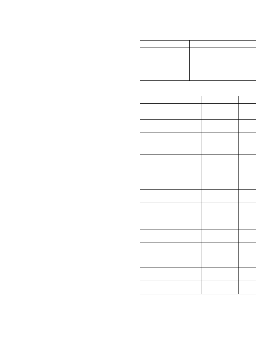
Table III. Summary of Jumper Functionality
Installed
Jumper Function
Jumper
JP1
Buffered Output A
JP2
50
Transformer Output
JP3 (STBY)
Unbuffered Output A
JP4
Unbuffered Output B
JP5
Buffered Output B
Table IV. AD768-EB Parts List
Reference
Value / Part Type Package
Qty/Bd
U1
AD768
28-Pin SOIC
1
U2
AD811
8-Pin DIP
1
T1
Mini-Circuits
Not Installed
1
T4–6T
A, B, CLOCK
BNC JACKs,
Small, Vertical
3
Small
JP1–5
Header
2-Pin
5
SW1, 2
SPDT, Secme
0.1"
× 0.3"
2
J1
40-Pin IDC
R.A., Male,
1
Connector
w/ Latches
R1
500
1/4 W, 0.01%,
1
Vishay
R2
25
1/4 W, 0.01%,
1
Vishay
R3, R13–21, &
R23–29
Wire Jumpers
17
R5
500
1/4 W, 0.01%,
1
Vishay
R7
100
1/4 W, 0.01%,
1
Vishay
R11
51
1/8 W, 5%, Carbon
1
R12
10 k
Pot.
3266 W
1
C1–4
1
F Ceram. Cap. Leaded
4
C5–8, C10, 12,
0.1
F Chip Cap,
14, & C16–19
1206
11
C9, 11, 13, 15
22
F Tant. Cap., Teardrop,
4
25 V
0.1" Spacing
Clock Input
An external sample clock must be provided to either the BNC
connector labeled “CLOCK” or on Pin 33 of the IDC connec-
tor. This clock must comply with the logic levels outlined in the
AD768 data sheet. The “CLOCK” input is terminated with a
removable 51
resistor. The IDC connector clock connection
is unterminated.
SW1. Clock source select switch. When SW1 is in position 1, Pin
33 of the IDC connected is applied to the CLOCK input of the
AD768. When SW2 is in position 2, the “CLOCK” BNC connec-
tor is applied to the CLOCK input of the AD768.
Digital Inputs
The digital inputs of the AD768, DB0–DB15, are available via
J1, a 40-pin IDC connector. These inputs should comply with
the specifications given in the AD768 data sheet.
Layout Considerations
Figures 28 and 29 show the AD768-EB ground and power
plane layouts. Figures 35–38 show the schematic diagram, trace
routing, silk screening, and component layout for the AD768 4
layer evaluation board.
Separate ground and power planes have several advantages for
high speed layouts. (For further information outlining these
advantages, see the application note “Design and Layout of a
Video Graphics System for Reduced EMI” [E1309] available
from Analog Devices [(617) 461-3392].) A solid ground plane
can be used if the digital return current can be routed such that
it does not modulate the analog ground plane. If this is not pos-
sible, it may be necessary to split the ground plane in order to
force currents to flow in a controlled direction. This type of
grounding scheme is shown in the Figure 28. The ground plane
is separated into analog and digital planes that are joined
together under the AD768. In any case, the AD768 should be
treated as an analog component and a common ground connec-
tion should be made underneath the AD768 despite some pins
being labeled “digital” ground and some as “analog” ground.
A complete parts list for the AD768 evaluation board is given in
Table IV.
相关PDF资料 |
PDF描述 |
|---|---|
| AD7543GKNZ | IC DAC 12BIT SRL INP MULT 16DIP |
| AD5570ARS | IC DAC 16BIT SRL-IN/VOUT 16-SSOP |
| MAX4396EUP+ | IC OP AMP R-R 20-TSSOP |
| AD5390BCPZ-3-REEL7 | IC DAC 14BIT 16CH 3V I2C 64LFCSP |
| AD5362BSTZ-REEL | IC DAC 16BIT 8CH SERIAL 52-LQFP |
相关代理商/技术参数 |
参数描述 |
|---|---|
| AD768-EB | 制造商:Analog Devices 功能描述:IC, 16-BIT 32 MSPS DAC - Bulk |
| AD768-EBZ | 制造商:Analog Devices 功能描述:EVAL BOARD - Boxed Product (Development Kits) |
| AD7690 | 制造商:AD 制造商全称:Analog Devices 功能描述:16-Bit Lower Power |
| AD76901 | 制造商:AD 制造商全称:Analog Devices 功能描述:14-Bit, 500 kSPS PulSAR ADC in MSOP |
| AD7690BCPZ-R2 | 制造商:Rochester Electronics LLC 功能描述: 制造商:Analog Devices 功能描述: |
发布紧急采购,3分钟左右您将得到回复。