- 您现在的位置:买卖IC网 > PDF目录8693 > AD7945BRZ-REEL (Analog Devices Inc)IC DAC 12BIT MULT PARALL 20SOIC PDF资料下载
参数资料
| 型号: | AD7945BRZ-REEL |
| 厂商: | Analog Devices Inc |
| 文件页数: | 2/16页 |
| 文件大小: | 0K |
| 描述: | IC DAC 12BIT MULT PARALL 20SOIC |
| 产品培训模块: | Data Converter Fundamentals DAC Architectures |
| 标准包装: | 1,000 |
| 设置时间: | 600ns |
| 位数: | 12 |
| 数据接口: | 并联 |
| 转换器数目: | 1 |
| 电压电源: | 单电源 |
| 功率耗散(最大): | 25µW |
| 工作温度: | -40°C ~ 85°C |
| 安装类型: | 表面贴装 |
| 封装/外壳: | 20-SOIC(0.295",7.50mm 宽) |
| 供应商设备封装: | 20-SOIC W |
| 包装: | 带卷 (TR) |
| 输出数目和类型: | 1 电流,单极;1 电流,双极 |
| 采样率(每秒): | 1.7M |
AD7943/AD7945/AD7948
REV. B
–10–
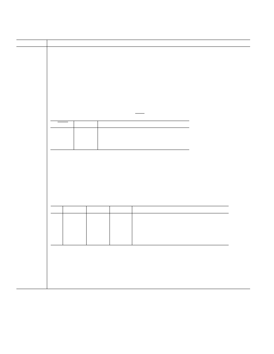
AD7948 PIN FUNCTION DESCRIPTIONS
Pin Mnemonic
Description
IOUT1
DAC current output terminal 1. Normally terminated at the virtual ground of output amplifier.
AGND
Analog Ground Pin. This pin connects to the back gates of the current steering switches. The DAC IOUT2
terminal is also connected internally to this point.
DGND
Digital Ground Pin.
CSMSB
Chip Select Most Significant Byte. Active Low Input. Used in combination with
WR to load external data into
the input register or in combination with
LDAC and WR to load external data into both input and DAC registers.
DF/
DOR
Data Format/Data Override. When this input is low, data in the DAC register is forced to one of two override
codes selected by CTRL. When the override signal is removed, the DAC output returns to reflect the value in
the DAC register. With DF/
DOR high, CTRL selects either a left or right justified input data format. For normal
operation, DF/
DOR is held high. See Table I.
CTRL
Control Input. See DF/
DOR description.
DB7–DB0
Digital Data Inputs.
LDAC
Load DAC input, active low. This signal, in combination with others, is used to load the DAC register from
either the input register or the external data bus.
CSLSB
Chip Select Least Significant (LS) Byte. Active Low Input. Used in combination with
WR to load external data
into the input register or in combination with
WR and LDAC to load external data into both input and DAC
registers.
WR
Write input, active low. This active low signal, in combination with others is used in loading external data into
the AD7948 input register and in transferring data from the input register to the DAC register.
VDD
Power supply input. This is nominally +5 V for Normal Mode Operation and +3.3 V to +5 V for Biased Mode
Operation.
VREF
DAC reference input.
RFB
DAC feedback resistor pin.
Table II. Truth Table for AD7948 Write Operation
WR
CSMSB
CSLSB
LDAC
Function
0
1
0
1
Load LS Byte to Input Register
0
1
0
Load LS Byte to Input Register and DAC Register
0
1
Load MS Byte to Input Register
0
1
0
Load MS Byte to Input Register and DAC Register
0
1
0
Load Input Register to DAC Register
1
X
No Data Transfer
Table I. Truth Table for DF/
DOR CTRL
DF/
DOR
CTRL
Function
0
DAC Register Contents Overridden by All 0s
0
1
DAC Register Contents Overridden by All 1s
1
0
Left-Justified Input Data Selected
1
Right-Justified Input Data Selected
相关PDF资料 |
PDF描述 |
|---|---|
| AD7945BRSZ-REEL | IC DAC 12BIT MULT PARALL 20SSOP |
| AD7945ARSZ-BREEL | IC DAC 12BIT MULT PARALL 20SSOP |
| CD4072BNSR | IC 4-IN OR GATE DUAL 14-SOP |
| VI-26F-IV-S | CONVERTER MOD DC/DC 72V 150W |
| VI-260-IV-S | CONVERTER MOD DC/DC 5V 150W |
相关代理商/技术参数 |
参数描述 |
|---|---|
| AD7945TQ | 制造商:Rochester Electronics LLC 功能描述:PARALLEL 12-B IOUT DAC IC - Bulk |
| AD7946 | 制造商:AD 制造商全称:Analog Devices 功能描述:14-Bit, 500 kSPS PulSAR⑩ ADC in MSOP/QFN |
| AD79461 | 制造商:AD 制造商全称:Analog Devices 功能描述:18-Bit, 2 MSPS PulSAR 15 mW ADC in LFCSP (QFN) |
| AD7946BCP | 制造商:Analog Devices 功能描述:ADC SGL SAR 500KSPS 14BIT SERL 10LFCSP EP - Bulk |
| AD7946BCPRL7 | 制造商:AD 制造商全称:Analog Devices 功能描述:14-Bit, 500 kSPS PulSAR⑩ ADC in MSOP/QFN |
发布紧急采购,3分钟左右您将得到回复。