- 您现在的位置:买卖IC网 > PDF目录5777 > AD8010ARZ-16-REEL7 (Analog Devices Inc)IC OPAMP CF 200MA LP 16SOIC PDF资料下载
参数资料
| 型号: | AD8010ARZ-16-REEL7 |
| 厂商: | Analog Devices Inc |
| 文件页数: | 3/12页 |
| 文件大小: | 0K |
| 描述: | IC OPAMP CF 200MA LP 16SOIC |
| 标准包装: | 400 |
| 放大器类型: | 电流反馈 |
| 电路数: | 1 |
| 转换速率: | 800 V/µs |
| -3db带宽: | 230MHz |
| 电流 - 输入偏压: | 10µA |
| 电压 - 输入偏移: | 5000µV |
| 电流 - 电源: | 15.5mA |
| 电流 - 输出 / 通道: | 200mA |
| 电压 - 电源,单路/双路(±): | 9 V ~ 12 V,±4.5 V ~ 6 V |
| 工作温度: | -40°C ~ 85°C |
| 安装类型: | 表面贴装 |
| 封装/外壳: | 16-SOIC(0.295",7.50mm 宽) |
| 供应商设备封装: | 16-SOIC W |
| 包装: | 带卷 (TR) |
AD8010
–11–
REV. B
Table I. –3 dB Bandwidth and Slew Rate vs. Closed-Loop
Gain and Resistor Values
Package: N-8
Closed-Loop
–3 dB BW
Slew Rate
Gain
RF ( )RG ( )
(MHz)
(V/ s)
+1
453
∞
285
900
+2
374
255
900
+5
348
86.6
200
800
+10
562
61.9
120
550
Package: R-16
Closed-Loop
–3 dB BW
Slew Rate
Gain
RF ( )RG ( )
(MHz)
(V/ s)
+1
412
∞
245
900
+2
392
220
900
+5
392
97.6
160
800
+10
604
66.5
95
550
Package: SO-8
Closed-Loop
–3 dB BW
Slew Rate
Gain
RF ( )RG ( )
(MHz)
(V/ s)
+1
392
∞
345
950
+2
374
305
1000
+5
348
86.6
220
1000
+10
499
54.9
135
650
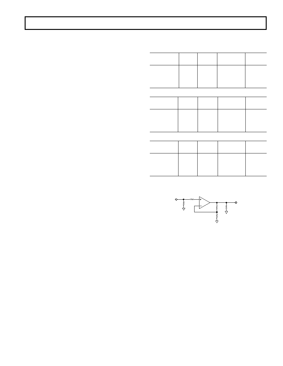
1. VO = 0.2 V p-p for –3 dB Bandwidth.
2. VO = 2 V p-p for Slew Rate.
3. Bypassing per Figure 29.
150
50
RF
RG
VOUT
18.75
VIN
Figure 32. Test Circuit for Table I
Closed-Loop Gain and Bandwidth
The AD8010 is a current feedback amplifier optimized for use
in high performance video and data acquisition applications.
Since it uses a current feedback architecture, its closed-loop
–3 dB bandwidth is dependent on the magnitude of the feedback
resistor. The desired closed-loop bandwidth and gain are obtained
by varying the feedback resistor (RF) to set the bandwidth, and
varying the gain resistor (RG) to set the desired gain. The char-
acteristic curves and specifications for this data sheet reflect the
performance of the AD8010 using the values of RF noted at the
top of the specifications table. If a greater –3 dB bandwidth
and/or slew rate is required (at the expense of video performance),
Table I provides the recommended resistor values. Figure 32
shows the test circuit and conditions used to produce Table I.
Effect of Feedback Resistor Tolerance on Gain Flatness
Because of the relationship between the 3 dB bandwidth and the
feedback resistor, the fine scale gain flatness will, to some extent,
vary with feedback resistor tolerance. It is therefore recommended
that resistors with a 1% tolerance be used if it is desired to main-
tain flatness over a wide range of production lots. In addition,
resistors of different construction have different associated para-
sitic capacitance and inductance. Metal-film resistors were used
for the bulk of the characterization for this data sheet. It is pos-
sible that values other than those indicated will be optimal for
other resistor types.
Quality of Coaxial Cable
Optimum flatness when driving a coax cable is possible only
when the driven cable is terminated at each end with a resistor
matching its characteristic impedance. If the coax was ideal,
then the resulting flatness would not be affected by the length of
the cable. While outstanding results can be achieved using inex-
pensive cables, it should be noted that some variation in flatness
due to varying cable lengths may be experienced.
相关PDF资料 |
PDF描述 |
|---|---|
| MVU14-8FBK | CONN TERM SPADE INS 16-14AWG #8 |
| AD8004ARZ-14-REEL | IC OPAMP CF QUAD LP LDIST 14SOIC |
| AD648KRZ-REEL | IC OPAMP BIFET 1MHZ DUAL 8SOIC |
| MVU14-8FFBK | CONN TERM SPADE INS 16-14AWG #8 |
| MVU14-4FB/SK | CONN FORK INSUL 16-14 AWG #4 |
相关代理商/技术参数 |
参数描述 |
|---|---|
| AD8010ARZ-REEL | 制造商:Analog Devices 功能描述:ADSL Driver Single 8-Pin SOIC N T/R |
| AD8011 | 制造商:AD 制造商全称:Analog Devices 功能描述:300 MHz, 1 mA Current Feedback Amplifier |
| AD8011_03 | 制造商:AD 制造商全称:Analog Devices 功能描述:300 MHz Current Feedback Amplifier |
| AD80112 | 制造商:Analog Devices 功能描述:N/A - Bulk |
发布紧急采购,3分钟左右您将得到回复。