- 您现在的位置:买卖IC网 > PDF目录373932 > AD8048AN (ANALOG DEVICES INC) 250 MHz, General Purpose Voltage Feedback Op Amps PDF资料下载
参数资料
| 型号: | AD8048AN |
| 厂商: | ANALOG DEVICES INC |
| 元件分类: | 音频/视频放大 |
| 英文描述: | 250 MHz, General Purpose Voltage Feedback Op Amps |
| 中文描述: | VIDEO AMPLIFIER, PDIP8 |
| 封装: | MINI, PLASTIC, DIP-8 |
| 文件页数: | 12/16页 |
| 文件大小: | 478K |
| 代理商: | AD8048AN |
REV. 0
–12–
AD8047/AD8048
THEORY OF OPERATION
General
The AD8047 and AD8048 are wide bandwidth, voltage feed-
back amplifiers. Since their open-loop frequency response fol-
lows the conventional 6 dB/octave roll-off, their gain bandwidth
product is basically constant. Increasing their closed-loop gain
results in a corresponding decrease in small signal bandwidth.
This can be observed by noting the bandwidth specification
between the AD8047 (gain of 1) and AD8048 (gain of 2).
Feedback Resistor Choice
The value of the feedback resistor is critical for optimum perfor-
mance on the AD8047 and AD8048. For maximum flatness at a
gain of 2, R
F
and R
G
should be set to 200
for the AD8048.
When the AD8047 is configured as a unity gain follower, R
F
should be set to 0
(no feedback resistor should be used) for
the plastic DIP and 66.5
for the SOIC.
V
IN
+V
S
6
7
2
4
3
V
OUT
G = 1 + R
F
R
G
AD8047/48
R
TERM
0.1
μ
F
10
μ
F
–V
S
0.1
μ
F
10
μ
F
R
G
R
F
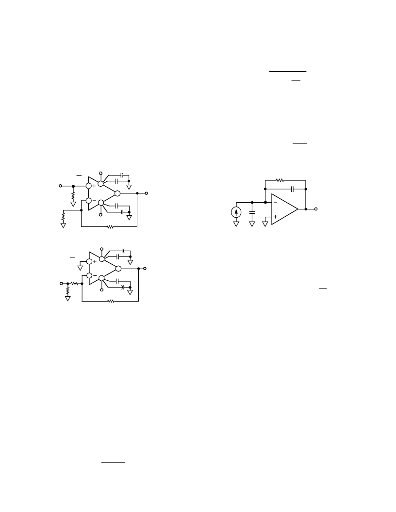
Figure 51. Noninverting Operation
V
IN
6
2
3
R
G
R
TERM
V
OUT
G = – R
F
R
G
AD8047/48
+V
S
7
0.1
μ
F
10
μ
F
4
–V
S
0.1
μ
F
10
μ
F
R
F
Figure 52. Inverting Operation
When the AD8047 is used in the transimpedance (I to V) mode,
such as in photodiode detection, the value of R
F
and diode
capacitance (C
I
) are usually known. Generally, the value of R
F
selected will be in the k
range, and a shunt capacitor (C
F
)
across R
F
will be required to maintain good amplifier stability.
The value of C
F
required to maintain optimal flatness (<1 dB
Peaking) and settling time can be estimated as:
[
where
ω
O
is equal to the unity gain bandwidth product of the
amplifier in rad/sec, and C
I
is the equivalent total input
capacitance at the inverting input. Typically
ω
O
= 800
×
10
6
rad/sec (see Open-Loop Frequency Response curve, Fig-
ure 17).
As an example, choosing R
F
= 10 k
and C
I
= 5 pF, requires
C
F
to be 1.1 pF (Note: C
I
includes both source and parasitic
circuit capacitance). The bandwidth of the amplifier can be
estimated using the C
F
calculated as:
C
F
(2
ω
O
C
I
R
F
–1)/
ω
O
2
R
F
2
]
1/2
f
3
dB
1.6
2
π
R
F
C
F
For general voltage gain applications, the amplifier bandwidth
can be closely estimated as:
f
3
dB
ω
O
2
π
1
+
R
F
R
G
This estimation loses accuracy for gains of +2/–1 or lower due
to the amplifier’s damping factor. For these “low gain” cases,
the bandwidth will actually extend beyond the calculated value
(see Closed-Loop BW plots, Figures 15 and 26).
As a rule of thumb, capacitor C
F
will not be required if:
(
R
F
i
R
G
)
×
C
I
≤
NG
4
ω
O
where
NG
is the Noise Gain (1 + R
F
/R
G
) of the circuit. For
most voltage gain applications, this should be the case.
R
F
V
OUT
AD8047
C
F
C
I
I
I
Figure 53. Transimpedance Configuration
Pulse Response
Unlike a traditional voltage feedback amplifier, where the slew
speed is dictated by its front end dc quiescent current and gain
bandwidth product, the AD8047 and AD8048 provide “on de-
mand” current that increases proportionally to the input “step”
signal amplitude. This results in slew rates (1000 V/
μ
s) compa-
rable to wideband current feedback designs. This, combined
with relatively low input noise current (1.0 pA/
√
Hz
), gives the
AD8047 and AD8048 the best attributes of both voltage and
current feedback amplifiers.
Large Signal Performance
The outstanding large signal operation of the AD8047 and
AD8048 is due to a unique, proprietary design architecture.
In order to maintain this level of performance, the maximum
180 V-MHz product must be observed, (e.g., @ 100 MHz,
V
O
≤
1.8 V p-p) on the AD8047 and 250 V-MHz product on
the AD8048.
Power Supply Bypassing
Adequate power supply bypassing can be critical when optimiz-
ing the performance of a high frequency circuit. Inductance in
the power supply leads can form resonant circuits that produce
peaking in the amplifier’s response. In addition, if large current
transients must be delivered to the load, then bypass capacitors
(typically greater than 1
μ
F) will be required to provide the best
settling time and lowest distortion. A parallel combination of at
least 4.7
μ
F, and between 0.1
μ
F and 0.01
μ
F, is recommended.
Some brands of electrolytic capacitors will require a small series
damping resistor
≈
4.7
for optimum results.
Driving Capacitive Loads
The AD8047/AD8048 have excellent cap load drive capability
for high speed op amps as shown in Figures 55 and 57. How-
ever, when driving cap loads greater than 25 pF, the best fre-
quency response is obtained by the addition of a small series
resistance. It is worth noting that the frequency response of the
相关PDF资料 |
PDF描述 |
|---|---|
| AD8048AR | 250 MHz, General Purpose Voltage Feedback Op Amps |
| AD8054ARU-REEL | Low Cost, High Speed Rail-to-Rail Amplifiers |
| AD8051AR-REEL | Low Cost, High Speed Rail-to-Rail Amplifiers |
| AD8054ARU | Low Cost, High Speed Rail-to-Rail Amplifiers |
| AD8054ARU-REEL7 | Low Cost, High Speed Rail-to-Rail Amplifiers |
相关代理商/技术参数 |
参数描述 |
|---|---|
| AD8048ANZ | 功能描述:IC OPAMP VF GP LDIST 50MA 8DIP RoHS:是 类别:集成电路 (IC) >> Linear - Amplifiers - Instrumentation 系列:- 标准包装:73 系列:Over-The-Top® 放大器类型:通用 电路数:4 输出类型:满摆幅 转换速率:0.07 V/µs 增益带宽积:200kHz -3db带宽:- 电流 - 输入偏压:1nA 电压 - 输入偏移:285µV 电流 - 电源:50µA 电流 - 输出 / 通道:25mA 电压 - 电源,单路/双路(±):2 V ~ 44 V,±1 V ~ 22 V 工作温度:-40°C ~ 85°C 安装类型:表面贴装 封装/外壳:16-WFDFN 裸露焊盘 供应商设备封装:16-DFN-EP(5x3) 包装:管件 |
| AD8048AR | 制造商:Analog Devices 功能描述:OP Amp Single Volt Fdbk 制造商:Analog Devices 功能描述:SEMICONDUCTORSLINEAR ((NS)) |
| AD8048AR-EBZ | 功能描述:BOARD EVAL FOR AD8048AR RoHS:是 类别:编程器,开发系统 >> 评估板 - 运算放大器 系列:- 产品培训模块:Lead (SnPb) Finish for COTS Obsolescence Mitigation Program 标准包装:1 系列:- |
| AD8048AR-REEL | 制造商:Analog Devices 功能描述:OP Amp Single Volt Fdbk ±6V 8-Pin SOIC N T/R |
| AD8048AR-REEL7 | 制造商:Analog Devices 功能描述:OP Amp Single Volt Fdbk 制造商:Analog Devices 功能描述:OP Amp Single Volt Fdbk ±6V 8-Pin SOIC N T/R 制造商:Rochester Electronics LLC 功能描述:G=2 STABLE V-FDBK OP AMP - Tape and Reel |
发布紧急采购,3分钟左右您将得到回复。