- 您现在的位置:买卖IC网 > PDF目录373941 > AD8210YRZ (ANALOG DEVICES INC) High Voltage, Bidirectional Current Shunt Monitor PDF资料下载
参数资料
| 型号: | AD8210YRZ |
| 厂商: | ANALOG DEVICES INC |
| 元件分类: | 电源管理 |
| 英文描述: | High Voltage, Bidirectional Current Shunt Monitor |
| 中文描述: | 1-CHANNEL POWER SUPPLY SUPPORT CKT, PDSO8 |
| 封装: | ROHS COMPLIANT, MS-012AA, SOIC-8 |
| 文件页数: | 14/16页 |
| 文件大小: | 287K |
| 代理商: | AD8210YRZ |
AD8210
APPLICATIONS
The AD8210 is ideal for high-side or low-side current sensing.
Its accuracy and performance benefits applications such as
3-phase and H-bridge motor control, solenoid control, as well
as power supply current monitoring.
Rev. 0 | Page 14 of 16
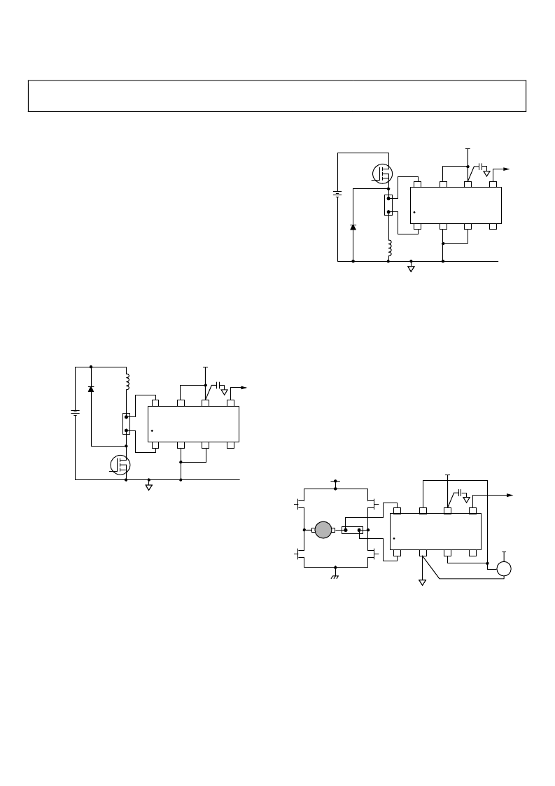
For solenoid control, two typical circuit configurations are used:
high-side current sense with a low-side switch, and high-side
current sense with a high-side switch.
HIGH-SIDE CURRENT SENSE WITH A LOW-SIDE
SWITCH
In this case, the PWM control switch is ground referenced. An
inductive load (solenoid) is tied to a power supply. A resistive
shunt is placed between the switch and the load (see Figure 33).
An advantage of placing the shunt on the high side is that the
entire current, including the recirculation current, can be meas-
ured because the shunt remains in the loop when the switch is
off. In addition, diagnostics can be enhanced because short circuits
to ground can be detected with the shunt on the high side.
0
INDUCTIVE
LOAD
CLAMP
DIODE
BATTERY
SHUNT
SWITCH
NC = NO CONNECT
5V
+IN
V
REF
1
+V
S
OUT
–IN
GND
V
REF
2
NC
AD8210
0.1μF
Figure 33. Low-Side Switch
In this circuit configuration, when the switch is closed, the
common-mode voltage moves down to the negative rail. When
the switch is opened, the voltage reversal across the inductive
load causes the common-mode voltage to be held one diode
drop above the battery by the clamp diode.
HIGH-SIDE CURRENT SENSE WITH A HIGH-SIDE
SWITCH
This configuration minimizes the possibility of unexpected
solenoid activation and excessive corrosion (see Figure 34). In
this case, both the switch and the shunt are on the high side.
When the switch is off, the battery is removed from the load,
which prevents damage from potential short circuits to ground,
while still allowing the recirculation current to be measured and
diagnostics to be preformed. Removing the power supply from
the load for the majority of the time minimizes the corrosive
effects that could be caused by the differential voltage between
the load and ground.
0
INDUCTIVE
LOAD
CLAMP
DIODE
BATTERY
SHUNT
SWITCH
NC = NO CONNECT
5V
+IN
V
REF
1
+V
S
OUT
–IN
GND
V
REF
2
NC
AD8210
0.1μF
Figure 34. High-Side Switch
Using a high-side switch connects the battery voltage to the
load when the switch is closed. This causes the common-mode
voltage to increase to the battery voltage. In this case, when the
switch is opened, the voltage reversal across the inductive load
causes the common-mode voltage to be held one diode drop
below ground by the clamp diode.
H-BRIDGE MOTOR CONTROL
Another typical application for the AD8210 is as part of the
control loop in H-bridge motor control. In this case, the AD8210
is placed in the middle of the H-bridge (see Figure 35) so that it
can accurately measure current in both directions by using the
shunt available at the motor. This configuration is beneficial for
measuring the recirculation current to further enhance the
control loop diagnostics.
0
SHUNT
2.5V
5V
CONTROLLER
NC = NO CONNECT
MOTOR
5V
+IN
V
REF
1
+V
S
OUT
–IN
GND
V
REF
2
NC
AD8210
0.1μF
Figure 35. Motor Control Application
The AD8210 measures current in both directions as the H-bridge
switches and the motor changes direction. The output of the
AD8210 is configured in an external reference bidirectional
mode; see the Modes of Operation section.
相关PDF资料 |
PDF描述 |
|---|---|
| AD8210YRZ-REEL | High Voltage, Bidirectional Current Shunt Monitor |
| AD8210YRZ-REEL7 | High Voltage, Bidirectional Current Shunt Monitor |
| AD8211 | High Voltage Current Shunt Monitor |
| AD8211YRJZ-R21 | High Voltage Current Shunt Monitor |
| AD8211YRJZ-RL1 | High Voltage Current Shunt Monitor |
相关代理商/技术参数 |
参数描述 |
|---|---|
| AD8210YRZ-REEL | 功能描述:IC CURRENT MONITOR 0.5% 8SOIC RoHS:是 类别:集成电路 (IC) >> PMIC - 稳流/电流管理 系列:- 产品培训模块:Lead (SnPb) Finish for COTS Obsolescence Mitigation Program 标准包装:50 系列:- 功能:电流开关 检测方法:- 精确度:±10% 输入电压:1.7 V ~ 5.5 V 电流 - 输出:600mA 工作温度:-40°C ~ 125°C 安装类型:表面贴装 封装/外壳:10-UFQFN 供应商设备封装:10-UTQFN(1.4x1.8) 包装:管件 |
| AD8210YRZ-REEL7 | 功能描述:IC CURRENT MONITOR 0.5% 8SOIC RoHS:是 类别:集成电路 (IC) >> PMIC - 稳流/电流管理 系列:- 产品培训模块:Lead (SnPb) Finish for COTS Obsolescence Mitigation Program 标准包装:50 系列:- 功能:电流开关 检测方法:- 精确度:±10% 输入电压:1.7 V ~ 5.5 V 电流 - 输出:600mA 工作温度:-40°C ~ 125°C 安装类型:表面贴装 封装/外壳:10-UFQFN 供应商设备封装:10-UTQFN(1.4x1.8) 包装:管件 |
| AD8211 | 制造商:AD 制造商全称:Analog Devices 功能描述:High Voltage Current Shunt Monitor |
| AD8211WYRJZ-R7 | 制造商:Analog Devices 功能描述:CURRENT SHUNT MONITOR 5PIN SOT-23 - Tape and Reel |
| AD8211WYRJZ-RL | 制造商:Analog Devices 功能描述: |
发布紧急采购,3分钟左右您将得到回复。