- 您现在的位置:买卖IC网 > PDF目录373943 > AD8313ARM (ANALOG DEVICES INC) 0.1 GHz-2.5 GHz, 70 dB Logarithmic Detector/Controller PDF资料下载
参数资料
| 型号: | AD8313ARM |
| 厂商: | ANALOG DEVICES INC |
| 元件分类: | 模拟信号调理 |
| 英文描述: | 0.1 GHz-2.5 GHz, 70 dB Logarithmic Detector/Controller |
| 中文描述: | SPECIALTY ANALOG CIRCUIT, PDSO8 |
| 封装: | MO-187AA, MSOP-8 |
| 文件页数: | 13/16页 |
| 文件大小: | 261K |
| 代理商: | AD8313ARM |
AD8313
–13–
REV. B
FREQUENCY – MHz
15
50
V10
5
0
–5
100
200
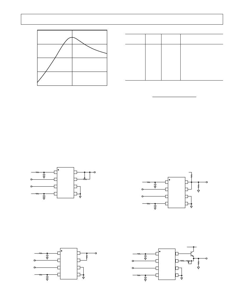
Figure 35. Voltage Response of 100 MHz Narrow-Band
Matching Network
Adjusting the Log Slope
Figure 36 shows how the log slope may be adjusted to an exact
value. The idea is simple: the output at pin VOUT is attenuated
by the variable resistor R2 working against the internal 18 k
of input resistance at the VSET pin. When R2 is zero, the
attenuation it introduces is zero, and thus the slope is the basic
18 mV/dB (note that this value varies with frequency, see
Figure 8). When R2 is set to its maximum value of 10 k
, the
attenuation from VOUT to VSET is the ratio 18/(18+10), and
the slope is raised to (28/18)
×
18 mV, or 28 mV/dB. At about
the midpoint, the nominal scale will be 23 mV/dB. Thus, a
70 dB input range will change the output by 70
×
23 mV, or
1.6 V.
18-30mV/dB
R2
10k
V
R3
10
V
0.1
m
F
R1
10
V
0.1
m
F
+V
S
+V
S
8
7
6
5
1
2
3
4
VPOS
AD8313
VOUT
INHI
INLO
VPOS PWDN
COMM
VSET
Figure 36. Adjusting the Log Slope
As already stated, the unadjusted log slope varies with frequency
from 17 mV/dB to 20 mV/dB, as shown in Figure 8. By placing
a resistor between VOUT and VSET, the slope can be adjusted
to a convenient 20 mV/dB as shown in Figure 37. Table II
shows the recommended values for this resistor R
EXT
. Also
shown are values for R
EXT
that increase the slope to approxi-
mately 50 mV/dB. The corresponding voltage swings for a
–65 dBm to 0 dBm input range are also shown in Table II.
20mV/dB
R
EXT
R3
10
V
0.1
m
F
R1
10
V
0.1
m
F
+V
S
+V
S
8
7
6
5
1
2
3
4
VPOS
AD8313
VOUT
INHI
INLO
VPOS PWDN
COMM
VSET
Figure 37. Adjusting the Log Slope to a Fixed Value
Table II. Values for R
EXT
in Figure 37
Frequency
MHz
R
EXT
k
V
Slope
mV/dB
V
OUT
Swing for Pin
–65 dBm to 0 dBm – V
100
900
1900
2500
100
900
1900
2500
0.953
2.00
2.55
0
29.4
32.4
33.2
26.7
20
20
20
20
50
50.4
49.8
49.7
0.44 to 1.74
0.58 to 1.88
0.70 to 2.00
0.54 to 1.84
1.10 to 4.35
1.46 to 4.74
1.74 to 4.98
1.34 to 4.57
The value for R
EXT
is calculated using the equation:
R
New Slope
Original Slope
Original Slope
EXT
=
(
)
–
×
18
k
The value for the
Original Slope
, at a particular frequency, can
be read from Figure 8. The resulting output swing is calculated
by simply inserting the
New Slope
value and the intercept at that
frequency (Figures 8 and 11) into the general equation for the
AD8313’s output voltage:
V
OUT
= Slope (P
IN
– Intercept)
Increasing Output Current
Where it is necessary to drive a more substantial load, one of
two methods can be used. In Figure 38, a 1 k
pull-up resistor
is added at the output which provides the load current necessary
to drive a 1 k
load to +1.7 V for V
S
= 2.7 V. The pull-up resis-
tor will slightly lower the intercept and the slope. As a result, the
transfer function of the AD8313 will be shifted upwards (inter-
cept shifts downward).
R2
10
V
0.1
m
F
R1
10
V
0.1
m
F
+V
S
+V
S
1
2
3
4
VPOS
AD8313
VOUT
INHI
INLO
VPOS PWDN
COMM
VSET
8
7
6
5
R
L
= 1k
V
20mV/dB
1k
V
+V
S
Figure 38. Increasing AD8313 Output Current Capability
In Figure 39, an emitter-follower is used to provide current
gain, when a 100
load can readily be driven to full-scale out-
put. While a high
β
transistor such as the BC848BLT1 (min
β
=
200) is recommended, a 2 k
pull-up resistor between VOUT
and +V
S
can provide additional base current to the transistor.
R3
10
V
0.1
m
F
R1
10
V
0.1
m
F
+V
S
+V
S
8
7
6
5
1
2
3
4
VPOS
AD8313
VOUT
INHI
INLO
VPOS PWDN
COMM
VSET
OUTPUT
+V
S
13k
V
R
L
100
V
10k
V
BC848BLT1
b
MIN
= 200
Figure 39. Output Current Drive Boost Connection
相关PDF资料 |
PDF描述 |
|---|---|
| AD8313ARM-REEL | 0.1 GHz-2.5 GHz, 70 dB Logarithmic Detector/Controller |
| AD8313-EVAL | 0.1 GHz-2.5 GHz, 70 dB Logarithmic Detector/Controller |
| AD8313 | 0.1 GHz-2.5 GHz,70dB Logarithmic Detector/Controller(频率为0.1 GHz-2.5 GHz,增益为70dB的对数检测器/控制器) |
| AD8314ARM | 100 MHz-2500 MHz 45 dB RF Detector/Controller |
| AD8314ARM-REEL | 100 MHz-2500 MHz 45 dB RF Detector/Controller |
相关代理商/技术参数 |
参数描述 |
|---|---|
| AD8313ARM | 制造商:Analog Devices 功能描述:Logarithmic Amplifier IC |
| AD8313ARM-REEL | 功能描述:IC LOG DETECTOR/CTRLR 8-MSOP RoHS:否 类别:RF/IF 和 RFID >> RF 检测器 系列:- 产品变化通告:Product Discontinuation 15/May/2006 标准包装:3,000 系列:- 频率:100MHz ~ 2GHz RF 型:手机,GSM,DCS,PCS 输入范围:- 精确度:- 电源电压:2.7 V ~ 5.5 V 电流 - 电源:300µA 包装:带卷 (TR) 封装/外壳:SC-74,SOT-457 其它名称:NCS5000SNT1GOS |
| AD8313ARM-REEL7 | 功能描述:IC LOG DETECTOR/CTRLR 8-MSOP RoHS:否 类别:RF/IF 和 RFID >> RF 检测器 系列:- 产品变化通告:Product Discontinuation 15/May/2006 标准包装:3,000 系列:- 频率:100MHz ~ 2GHz RF 型:手机,GSM,DCS,PCS 输入范围:- 精确度:- 电源电压:2.7 V ~ 5.5 V 电流 - 电源:300µA 包装:带卷 (TR) 封装/外壳:SC-74,SOT-457 其它名称:NCS5000SNT1GOS |
| AD8313ARMZ | 功能描述:IC LOGARTIHMIC AMP 70DB 8-MSOP RoHS:是 类别:RF/IF 和 RFID >> RF 检测器 系列:- 产品变化通告:Product Discontinuation 15/May/2006 标准包装:3,000 系列:- 频率:100MHz ~ 2GHz RF 型:手机,GSM,DCS,PCS 输入范围:- 精确度:- 电源电压:2.7 V ~ 5.5 V 电流 - 电源:300µA 包装:带卷 (TR) 封装/外壳:SC-74,SOT-457 其它名称:NCS5000SNT1GOS |
| AD8313ARMZ | 制造商:Analog Devices 功能描述:IC DETECTOR/CONTROLLER 制造商:Analog Devices 功能描述:IC, DETECTOR/CONTROLLER |
发布紧急采购,3分钟左右您将得到回复。