- 您现在的位置:买卖IC网 > PDF目录10831 > AD834JRZ (Analog Devices Inc)IC MULTIPLIER 4-QUADRANT 8-SOIC PDF资料下载
参数资料
| 型号: | AD834JRZ |
| 厂商: | Analog Devices Inc |
| 文件页数: | 4/20页 |
| 文件大小: | 0K |
| 描述: | IC MULTIPLIER 4-QUADRANT 8-SOIC |
| 标准包装: | 1 |
| 功能: | 模拟乘法器 |
| 位元/级数: | 四象限 |
| 封装/外壳: | 8-SOIC(0.154",3.90mm 宽) |
| 供应商设备封装: | 8-SO |
| 包装: | 管件 |
| 产品目录页面: | 789 (CN2011-ZH PDF) |
AD834
Data Sheet
Rev. F | Page 12 of 20
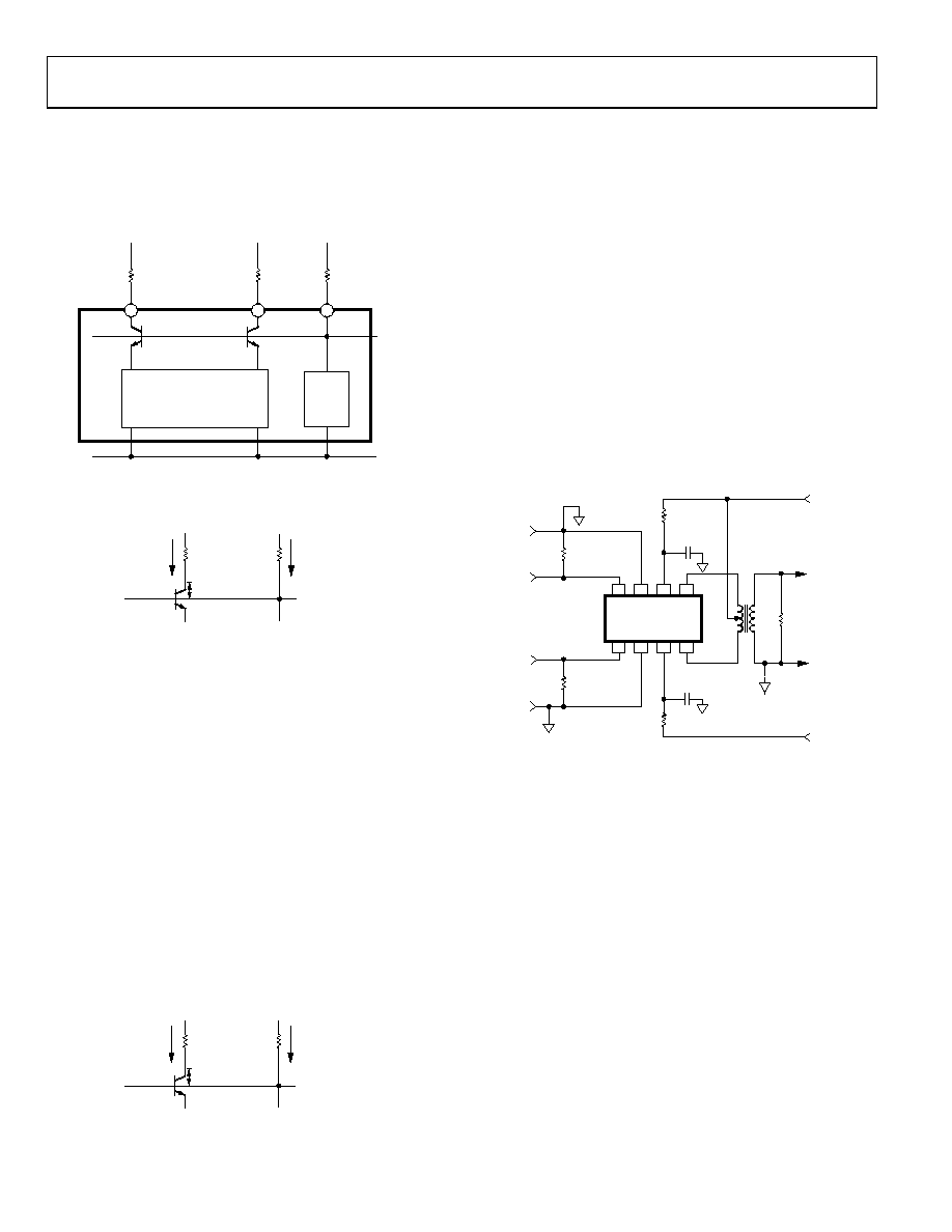
BIASING THE OUTPUT
The AD834 has two open collector outputs as shown in Figure 13.
The +VS pin, Pin 6, is tied to the base of the output NPN
transistors. The following general guidelines maximize
performance of the AD834.
+VS
MULTIPLIER
CORE
–VS
W1
W2
+5V
RW
49.9
Ω
RW
49.9
Ω
RCC
75
Ω
BIAS
–5V
OUTPUT OF AD834
AD834
5
4
6
00894-
1
13
Figure 13. Output Stage Block Diagram
12.5mA
RW
W COLLECTOR
HEADROOM
–
+
W BASE
RCC
+5V
+VS
NEGATIVE OUTPUT
VOTLAGE SWING
SITUATION 1
IPOS SUPPLY
8.0mA TO 14mA
(GENERALLY 10.5mA)
00894-
1
14
Figure 14. Negative Swing
Figure 14 shows the currents at the input when the AD834
swings negative. Generally, +VS should be biased at +4 V or
higher. For best performance, use resistor values that do not
saturate the output transistors. Allowing for adequate transistor
headroom reduces distortion.
Headroom = Voltage at WCOLLECTOR Voltage at WBASE
When either output swings negative, the maximum current
flows through the RW resistors. It is in this situation that
headroom is at a minimum.
HeadroomNEGATIVE SWING = (IPOS SUPPLY × RCC) (12.5 mA × RW)
Try to keep headroom at or above 200 mV to maintain adequate
range. Headroom ≥ 200 mV.
This recommendation addresses the positive swing of the
output as shown in Figure 15. It is sometimes difficult to meet
this for negative output swing.
4.5mA
RW
W COLLECTOR
HEADROOM
–
+
W BASE
RCC
+5V
+VS
POSITIVE OUTPUT
VOTLAGE SWING
IPOS SUPPLY
8.0mA TO 14mA
(GENERALLY 10.5mA)
00894-
1
15
SITUATION 2
Figure 15. Positive Output Swing
The current through RW is smaller for positive output swings.
HeadroomPOSITIVE SWING = (IPOS SUPPLY × RCC) (4.5 mA × RW)
For dc applications or applications where distortion is not a
concern, the headroom may be zero or as low as 200 mV.
However, for most cases, size the resistors to give the output
adequate headroom.
TRANSFORMER COUPLING
In many high frequency applications where baseband operation
is not required at either inputs or the output, transformer coupling
can be used. Figure 16 shows the use of a center-tapped output
transformer, which provides the necessary dc load condition
at the outputs, W1 and W2, and is designed to match into the
desired load impedance by appropriate choice of turns ratio.
The specific choice of the transformer design depends entirely
on the application. Transformers can also be used at the inputs.
Center-tapped transformers can reduce high frequency distortion
and lower HF feedthrough by driving the inputs with balanced
signals.
00894-
012
8
7
6
5
1
2
3
4
X2
X1 +VS W1
Y1
Y2
–VS W2
AD834
X-INPUT
±1V FS
Y-INPUT
±1V FS
TERMINATION
RESISTOR
TERMINATION
RESISTOR
49.9
+5V
4.7
–5V
LOAD
1F
CERAMIC
1F
CERAMIC
Figure 16. Transformer-Coupled Output
A particularly effective type of transformer is the balun1, which
is a short length of transmission line wound onto a toroidal
ferrite core. Figure 17 shows this arrangement used to convert
the bal(anced) output to an un(balanced) one (therefore, the
use of the term). Although the symbol used is identical to that
for a transformer, the mode of operation is quite different. First,
the load should now be equal to the characteristic impedance of
the line (although this is usually not critical for short line lengths).
The collector load resistors, RW, can also be chosen to reverse-
terminate the line, but again this is only necessary when an
electrically long line is used. In most cases, RW is made as large
as the dc conditions allow to minimize power loss to the load.
The line can be a miniature coaxial cable or a twisted pair.
1 For a good treatment of baluns, see Transmission Line Transformers by Jerry
Sevick; American Radio Relay League publication.
相关PDF资料 |
PDF描述 |
|---|---|
| AD734ANZ | IC MULT/DIV 4-QUADRANT 14-DIP |
| AD632AHZ | IC PREC MULTIPLIER MONO TO100-10 |
| AD835ARZ | IC MULTIPLIER 4-QUADRANT 8-SOIC |
| AD633JRZ-R7 | IC MULTIPLIER ANALOG 8SOIC |
| AD633ANZ | IC ANALOG MULTIPLIER 8-DIP |
相关代理商/技术参数 |
参数描述 |
|---|---|
| AD834JRZ | 制造商:Analog Devices 功能描述:ANALOG MULTIPLIER IC |
| AD834JRZ-R7 | 功能描述:IC MULTIPLIER 4-QUADRANT 8-SOIC RoHS:是 类别:集成电路 (IC) >> 线性 - 模拟乘法器,除法器 系列:- 标准包装:25 系列:HA 功能:模拟乘法器 位元/级数:四象限 封装/外壳:16-CDIP(0.300",7.62mm) 供应商设备封装:16-CDIP 侧面铜焊 包装:管件 |
| AD834JRZ-RL | 功能描述:IC MULTIPLIER 4-QUADRANT 8-SOIC RoHS:是 类别:集成电路 (IC) >> 线性 - 模拟乘法器,除法器 系列:- 标准包装:25 系列:HA 功能:模拟乘法器 位元/级数:四象限 封装/外壳:16-CDIP(0.300",7.62mm) 供应商设备封装:16-CDIP 侧面铜焊 包装:管件 |
| AD834S | 制造商:AD 制造商全称:Analog Devices 功能描述:500 MHz Four-Quadrant Multiplier |
| AD834SQ/883B | 功能描述:增效器/分频器 WIDEBAND MULTIPLIER IC RoHS:否 制造商:Texas Instruments 产品:Multiplier 逻辑系列: 工作电源电压: 最大工作温度:+ 85 C 最小工作温度:- 40 C 安装风格:Through Hole 封装 / 箱体:PDIP-14 |
发布紧急采购,3分钟左右您将得到回复。