参数资料
| 型号: | AD8428ARZ |
| 厂商: | Analog Devices Inc |
| 文件页数: | 10/20页 |
| 文件大小: | 0K |
| 描述: | IC AMP INSTRUMENTATON 8SOIC |
| 标准包装: | 1 |
| 放大器类型: | 仪表 |
| 电路数: | 1 |
| 转换速率: | 50 V/µs |
| -3db带宽: | 3.5MHz |
| 电流 - 输入偏压: | 200nA |
| 电压 - 输入偏移: | 100µV |
| 电流 - 电源: | 6.5mA |
| 电流 - 输出 / 通道: | 30mA |
| 电压 - 电源,单路/双路(±): | ±4 V ~ 18 V |
| 工作温度: | -40°C ~ 85°C |
| 安装类型: | 表面贴装 |
| 封装/外壳: | 8-SOIC(0.154",3.90mm 宽) |
| 供应商设备封装: | 8-SO |
| 包装: | 管件 |
AD8428
Data Sheet
Rev. A | Page 18 of 20
APPLICATIONS INFORMATION
The classic 3-op-amp topology used for instrumentation
amplifiers typically places all the gain in the first stage and
subtracts the common-mode signals only in the second stage.
When operated at high gain, any amplifier is sensitive to large
interfering signals that can saturate it, thus making it impossible
to recover the signal of interest.
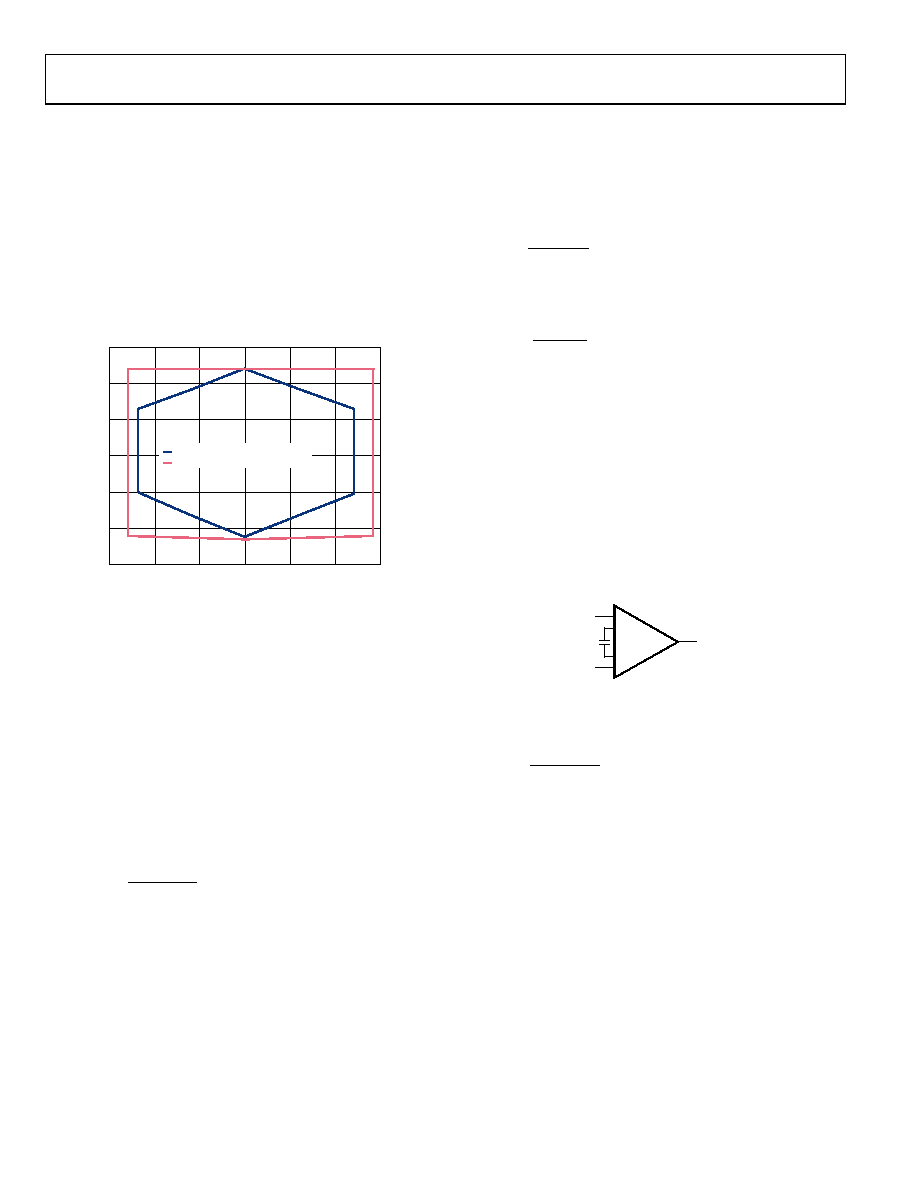
The AD8428 splits the total gain of 2000 into two stages: 200 in the
preamplification stage and 10 in the subtractor stage. Reducing the
gain of the first stage helps to increase the common-mode range
vs. differential signal range by avoiding saturation of the preamps.
–15
–10
–5
0
5
10
15
–15
–10
–5
0
5
10
15
INP
U
T
CO
M
O
N-
M
O
D
E
V
O
LT
AG
E
(
V
)
OUTPUT VOLTAGE (V)
SINGLE STAGE GAIN, G = 2000
AD8428
0973
1-
246
Figure 46. AD8428 vs. Single Stage Gain Topology, G = 2000
In addition, filtering between stages can help to attenuate signals
before they reach the second amplification stage. This filtering
helps to prevent saturation of the second stage amplifier as long
as the signals are located in frequencies other than the signal of
interest.
EFFECT OF PASSIVE NETWORK ACROSS THE
FILTER TERMINALS
The AD8428 filter terminals allow access between the two
amplification stages. Adding a passive network between the two
terminals can shape the transfer function over the frequency of
the amplifier. The general expression for the transfer function is
represented by Equation 1.
6000
2000
+
×
=
Z(s)
G(s)
(1)
where Z(s) is the frequency dependent impedance of the
network across the filter terminals.
CIRCUITS USING THE FILTER TERMINALS
Setting the Amplifier to Different Gains
In its simplest form, the transfer function equation (Equation 1)
implies that the AD8428 can be configured for gains lower than
2000. This can be achieved by attaching a resistor across the filter
pins. Unlike the gain configuration of traditional instrumentation
amplifiers, this resistor attenuates the signal that was previously
amplified by the initial gain of 200.
Because this resistor appears inside the feedback of the subtractor
stage, it modifies the gain of the subtractor as well. The total gain
formula is a simplified version of the transfer function equation
(Equation 1).
6000
2000
+
×
=
G
R
G
(2)
The RG unit is in ohms. The resistor value required to obtain the
desired gain can be calculated using the following formula:
G
R
G
×
=
2000
6000
The AD8428 defaults to G = 2000 when no gain resistor is used.
When setting the amplifier to a different gain, the absolute gain
accuracy is only 10%. In addition, the temperature mismatch of
the external gain resistor increases the gain drift of the instrumen-
tation amplifier. Gain error and gain drift are at a guaranteed
minimum when a gain resistor is not used. For applications that
require accuracy at different gains, low noise, and wide bandwidth,
the AD8429 should be considered.
Low-Pass Filter
To help limit undesired differential signals, a first-order, low-pass
filter can be implemented by adding a capacitor across the filter
+IN
–IN
+
–
AD8428
OUT
CF
+FIL
–FIL
09
73
1-
1
46
Figure 47. Differential Low-Pass Filter
This single-pole filter limits the signal bandwidth, as shown in
the following equation:
F
C
f
)
k
6
(
2
1
Ω
π
=
The 6 kΩ factor comes from the internal resistor values. The
tolerance of these resistors is 10%; therefore, using capacitors
with a tolerance better than 5% does not provide a significant
improvement on the absolute tolerance of the cutoff frequency.
Limiting the bandwidth of the amplifier also helps to minimize
the amount of out-of-band noise present at the output.
Note that filtering common-mode signals by adding a capacitor
on each filter terminal to ground degrades the performance of
the amplifier. This practice is generally discouraged because it
degrades CMRR performance. In addition, filtering common-
mode signals has little effect on preventing the saturation of the
internal nodes. On the contrary, the load added to the preamplifiers
causes them to saturate with even smaller common-mode signals.
相关PDF资料 |
PDF描述 |
|---|---|
| 78548-214HLF | BERGSTIK II DR STRAIGHT RET |
| 951206-7722-AR | CONN HEADER 6POS 2MM R/A SOLDER |
| TSW-148-14-L-D | CONN HEADER 96POS .100" DL GOLD |
| 77311-124-05LF | BERGSTIK |
| TSW-148-08-L-D | CONN HEADER 96POS .100" DL GOLD |
相关代理商/技术参数 |
参数描述 |
|---|---|
| AD8428ARZ_PROMO | 制造商:Analog Devices 功能描述:IC AMP INSTR LOW NOISE SOI |
| AD8428ARZ-RL | 功能描述:IC AMP INSTRUMENTATON 8SOIC RoHS:是 类别:集成电路 (IC) >> Linear - Amplifiers - Instrumentation 系列:- 标准包装:2,500 系列:Excalibur™ 放大器类型:J-FET 电路数:1 输出类型:- 转换速率:45 V/µs 增益带宽积:10MHz -3db带宽:- 电流 - 输入偏压:20pA 电压 - 输入偏移:490µV 电流 - 电源:1.7mA 电流 - 输出 / 通道:48mA 电压 - 电源,单路/双路(±):4.5 V ~ 38 V,±2.25 V ~ 19 V 工作温度:-40°C ~ 85°C 安装类型:表面贴装 封装/外壳:8-SOIC(0.154",3.90mm 宽) 供应商设备封装:8-SOIC 包装:带卷 (TR) |
| AD8428BRZ | 功能描述:IC OPAMP INST 3.5MHZ LN 8SOIC RoHS:是 类别:集成电路 (IC) >> Linear - Amplifiers - Instrumentation 系列:- 标准包装:2,500 系列:Excalibur™ 放大器类型:J-FET 电路数:1 输出类型:- 转换速率:45 V/µs 增益带宽积:10MHz -3db带宽:- 电流 - 输入偏压:20pA 电压 - 输入偏移:490µV 电流 - 电源:1.7mA 电流 - 输出 / 通道:48mA 电压 - 电源,单路/双路(±):4.5 V ~ 38 V,±2.25 V ~ 19 V 工作温度:-40°C ~ 85°C 安装类型:表面贴装 封装/外壳:8-SOIC(0.154",3.90mm 宽) 供应商设备封装:8-SOIC 包装:带卷 (TR) |
| AD8428BRZ_PROMO | 制造商:Analog Devices 功能描述:INST AMP 3.5MHZ 2K V/V 0.2 |
| AD8428BRZ-RL | 功能描述:IC OPAMP INST 3.5MHZ LN 8SOIC RoHS:是 类别:集成电路 (IC) >> Linear - Amplifiers - Instrumentation 系列:- 标准包装:2,500 系列:Excalibur™ 放大器类型:J-FET 电路数:1 输出类型:- 转换速率:45 V/µs 增益带宽积:10MHz -3db带宽:- 电流 - 输入偏压:20pA 电压 - 输入偏移:490µV 电流 - 电源:1.7mA 电流 - 输出 / 通道:48mA 电压 - 电源,单路/双路(±):4.5 V ~ 38 V,±2.25 V ~ 19 V 工作温度:-40°C ~ 85°C 安装类型:表面贴装 封装/外壳:8-SOIC(0.154",3.90mm 宽) 供应商设备封装:8-SOIC 包装:带卷 (TR) |
发布紧急采购,3分钟左右您将得到回复。