- 您现在的位置:买卖IC网 > PDF目录1895 > AD9980KSTZ-95 (Analog Devices Inc)IC INTERFACE 8BIT ANALOG 80LQFP PDF资料下载
参数资料
| 型号: | AD9980KSTZ-95 |
| 厂商: | Analog Devices Inc |
| 文件页数: | 10/44页 |
| 文件大小: | 0K |
| 描述: | IC INTERFACE 8BIT ANALOG 80LQFP |
| 标准包装: | 90 |
| 应用: | 视频 |
| 接口: | 模拟 |
| 电源电压: | 3.13 V ~ 3.47 V |
| 封装/外壳: | 80-LQFP |
| 供应商设备封装: | 80-LQFP(14x14) |
| 包装: | 管件 |
| 安装类型: | 表面贴装 |
| 配用: | AD9980/PCBZ-ND - KIT EVALUATION AD9980 |
第1页第2页第3页第4页第5页第6页第7页第8页第9页当前第10页第11页第12页第13页第14页第15页第16页第17页第18页第19页第20页第21页第22页第23页第24页第25页第26页第27页第28页第29页第30页第31页第32页第33页第34页第35页第36页第37页第38页第39页第40页第41页第42页第43页第44页
AD9980
Preliminary Technical Data
Rev. 0 | Page 18 of 44
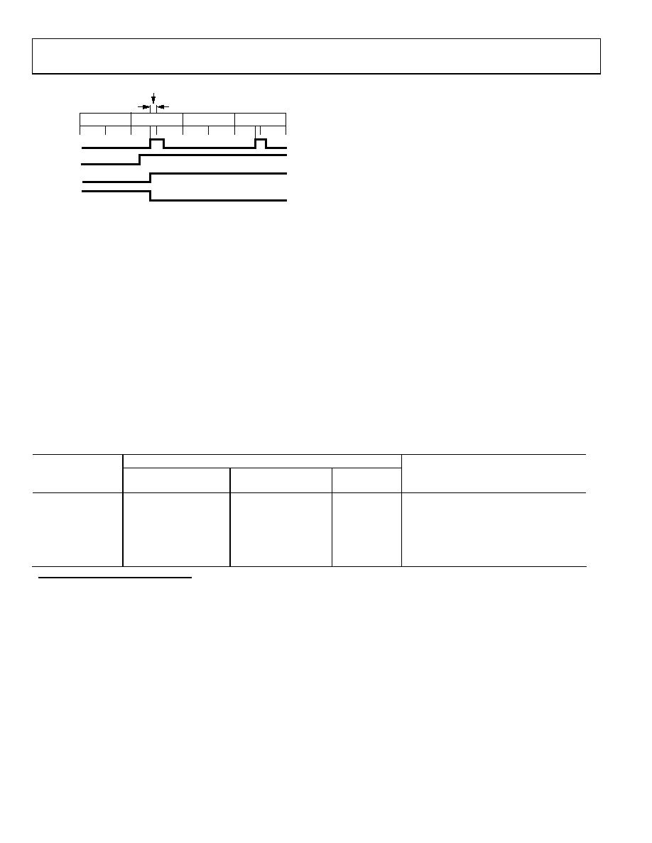
FIELD 1
FIELD 0
SYNC SEPARATOR THRESHOLD
FIELD 1
FIELD 0
23
2
1
4
31
HSYNCIN
VSYNCIN
VSYNCOUT
O/E FIELD
EVEN FIELD
QUADRANT
04740-018
Figure 12. Vsync Filter—Odd/Even
Power Management
To meet display requirements for low standby power, the
AD9980 includes a power-down mode. The power-down state
can be controlled manually (with Pin 17 or Register 0x1E, Bit 3),
or completely automatically by the chip. If automatic control is
selected (0x1E, Bit 4), the AD9980’s decision is based on the
status of the sync detect bits (Register 0x24, Bits 2, 3, 6,
and 7). If either an Hsync or a sync-on-green input is detected
on any input, the chip powers up, otherwise it powers down. If
manual control is desired, the AD9980 includes the flexibility of
control with both a dedicated pin and a register bit. The dedi-
cated pin allows a hardware watchdog circuit to control power-
down, while the register bit allows power-down to be controlled
by software. With manual power-down control, the polarity of
the power-down pin must be set (0x1E, Bit 2) regardless of
whether the pin is used. If unused, it is recommended to set the
polarity to active high and hardwire the pin to ground with a
10 k resistor.
In power-down mode, there are several circuits that continue to
operate normally. The serial register and sync detect circuits
maintain power so that the AD9980 can be woken up from
its power-down state. The bandgap circuit maintains power
because it is needed for sync detection. The sync-on-green and
SOGOUT functions continue to operate because the SOGOUT
output is needed when sync detection is performed by a
secondary chip. All of these circuits require minimal power to
operate. Typical standby power on the AD9980 is about 50 mW.
There are two options that can be selected when in power-
down. These are controlled by Bits 0 and 1 in Register 0x1E. The
first is to determine whether the SOGOUT pin is put in high
impedance or not. In most cases, SOGOUT is not put in high
impedance during normal operation. The option to put
SOGOUT in high impedance is included mainly to allow for
factory testing modes. The second option is to keep the AD9980
powered up and only put the outputs in high impedance. This
option is useful when the data outputs from two chips are
connected on a PCB and the user wants to switch
instantaneously between the two.
Table 10.Power-Down Control and Mode Descriptions
Inputs
Mode
Auto Power-Down
Control1
Power-Down2
Sync Detect3
Powered-On or Comments
Power-Up
1
X
1
Everything
Power-Down
1
X
0
Only the serial bus, sync activity detect,
SOG, bandgap reference
Power-Up
0
X
Everything
Power-Down
0
1
X
Only the serial bus, sync activity detect,
SOG, bandgap reference
1 Auto power-down control is set by Register 0x1E, Bit 4.
2 Power-down is controlled by OR’ing Pin 17 with Register 0x1E, Bit 3. The polarity of Pin 17 is set by Register 0x1E, Bit 2.
3 Sync detect is determined by OR’ing Register 0x24, Bits 2, 3, 6, and 7.
相关PDF资料 |
PDF描述 |
|---|---|
| AD9981KSTZ-95 | IC INTERFACE 10BIT ANALOG 80LQFP |
| AD9983AKSTZ-170 | IC DISPLAY 8BIT 170MSPS 80LQFP |
| AD9985KSTZ-140 | IC INTERFACE 8BIT 140MSPS 80LQFP |
| AD9990BBCZ | IC CCD SGNL PROCESSOR 112CSPBGA |
| AD9991KCPZRL | IC CCD SIGNAL PROCESSOR 56-LFCSP |
相关代理商/技术参数 |
参数描述 |
|---|---|
| AD9980KSTZ-RL95 | 制造商:Analog Devices 功能描述: |
| AD9980PCB | 制造商:AD 制造商全称:Analog Devices 功能描述:High Performance 8-Bit Display Interface |
| AD9981 | 制造商:AD 制造商全称:Analog Devices 功能描述:High Performance 10-Bit Display Interface |
| AD9981/PCB | 制造商:AD 制造商全称:Analog Devices 功能描述:High Performance 10-Bit Display Interface |
| AD9981/PCBZ | 制造商:Analog Devices 功能描述:Evaluation Board For The High Performance 10-Bit Display Interface 制造商:Analog Devices 功能描述:EVAL BD FOR THE HI-PERF 10-BIT DISPLAY INTRFC - Bulk |
发布紧急采购,3分钟左右您将得到回复。