- 您现在的位置:买卖IC网 > PDF目录11767 > AD9983AKCPZ-170 (Analog Devices Inc)IC INTRFACE 8BIT 170MSPS 64LFCSP PDF资料下载
参数资料
| 型号: | AD9983AKCPZ-170 |
| 厂商: | Analog Devices Inc |
| 文件页数: | 4/44页 |
| 文件大小: | 0K |
| 描述: | IC INTRFACE 8BIT 170MSPS 64LFCSP |
| 标准包装: | 1 |
| 应用: | 视频 |
| 接口: | 模拟 |
| 电源电压: | 1.7 V ~ 3.47 V |
| 封装/外壳: | 64-VFQFN 裸露焊盘,CSP |
| 供应商设备封装: | 64-LFCSP-VQ(9x9) |
| 包装: | 管件 |
| 安装类型: | 表面贴装 |
第1页第2页第3页当前第4页第5页第6页第7页第8页第9页第10页第11页第12页第13页第14页第15页第16页第17页第18页第19页第20页第21页第22页第23页第24页第25页第26页第27页第28页第29页第30页第31页第32页第33页第34页第35页第36页第37页第38页第39页第40页第41页第42页第43页第44页
AD9983A
Rev. 0 | Page 12 of 44
Negative target codes are included in order to duplicate a fea-
ture that is present with manual offset adjustment. The benefit
that is being mimicked is the ability to easily adjust brightness
on a display. By setting the target code to a value that does not
correspond to the ideal ADC range, the end result is an image
that is either brighter or darker. A target code higher than ideal
results in a brighter image. A target code lower than ideal
results in a darker image.
The ability to program a target code gives a large degree of
freedom and flexibility. In most cases all channels are set to
either 1 or 128, but the flexibility to select other values allows
for the possibility of inserting intentional skews between
channels. It also allows the ADC range to be skewed so that
voltages outside of the normal range can be digitized. For
example, setting the target code to 40 allows the sync tip, which
is normally below black level, to be digitized and evaluated.
The internal logic for the auto-offset circuit requires 16 data
clock cycles to perform its function. This operation is executed
immediately after the clamping pulse. Therefore, it is important
to end the clamping pulse signal at least 16 data clock cycles
before active video. This is true whether using the AD9983A
internal clamp circuit or an external clamp signal. The auto-
offset function can be programmed to run continuously or on a
one-time basis (see auto-offset hold, Register 0x2C, Bit 4). In
continuous mode, the update frequency can be programmed
(Register 0x1B, Bits[4:3]). Continuous operation with updates
every 64 Hsyncs is recommended.
A guideline for basic auto-offset operation is shown in Table 6
and Table 7.
Table 6. RGB Auto-Offset Register Settings
Register
Value
Comments
0x0B
0x02
Sets red target to 4
0x0C
0x00
Must be written
0x0D
0x02
Sets green target to 4
0x0E
0x00
Must be written
0x0F
0x02
Sets blue target to 4
0x10
0x00
Must be written
0x18, Bits[3:1]
000
Sets red, green, and blue
channels to ground clamp
0x1B, Bits[5:3]
110
Selects update rate and
enables auto-offset.
Table 7. PbPr Auto-Offset Register Settings
Register
Value
Comments
0x0B
0x40
Sets Pr (red) target to 128
0x0C
0x00
Must be written
0x0D
0x02
Sets Y (green) target to 4
0x0E
0x00
Must be written
0x0F
0x40
Sets Pb (blue) target to 128
0x10
0x00
Must be written
0x18 Bits[3:1]
101
Sets Pb, Pr to midscale clamp
and Y to ground clamp
0x1B, Bits[5:3]
110
Selects update rate and
enables auto-offset
Automatic Gain Matching
The AD9983A includes circuitry to match the gains between
the three channels to within 1% of each other. Matching the
gains of each channel is necessary in order to achieve good
color balance on a display. On products without this feature,
gain matching is achieved by writing software that evaluates the
output of each channel, calculates gain mismatches, then writes
values to the gain registers of each channel to compensate. With
the auto gain matching function, this software routine is no
longer needed. To activate auto gain matching, set Register 0x3C,
Bit 2 to Bit 1.
Auto gain matching has similar timing requirements to auto
offset. It requires 16 data clock cycles to perform its function,
starting immediately after the end of the clamp pulse. Unlike
auto offset it does not require that these 16 clock cycles occur
during the back porch reference time, although that is what is
recommended. During auto gain matching operation, the data
outputs of the AD9983A are frozen (held at the value they had
just prior to operation). The auto gain matching function can be
programmed to run continuously or on a one-time basis (see
the 0x3C—Bit[3] Auto Gain Matching Hold section).
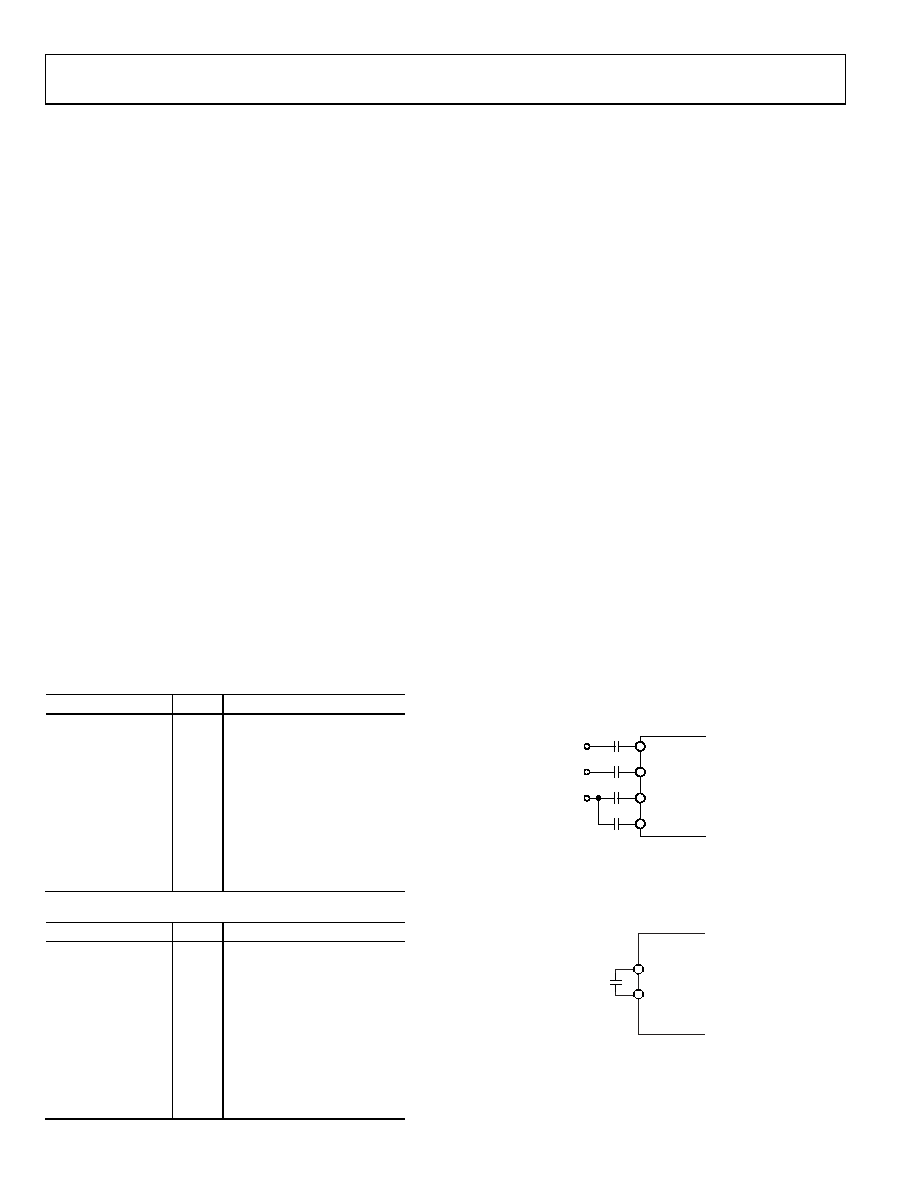
SYNC-ON-GREEN
The sync-on-green inputs (SOGIN0, SOGIN1) operate in two
steps. First, they set a baseline clamp level off of the incoming
video signal with a negative peak detector. Second, they set the
sync trigger level to a programmable (Register 0x1D, Bits[7:3])
level (typically 128 mV) above the negative peak. The sync-on-
green inputs must be ac-coupled to the green analog input
through their own capacitors. The value of the capacitors must
be 1 nF ±20%. If sync-on-green is not used, this connection is
not required. The sync-on-green signal always has negative
polarity.
RAIN
BAIN
GAIN
SOGIN
47nF
1nF
06
47
5-
00
4
Figure 4. Typical Input Configuration
REFERENCE BYPASSING
REFLO and REFHI are connected to each other by a 10 μF
capacitor. These references are used by the input ADC circuitry.
REFHI
REFLO
10F
064
75-
01
4
Figure 5. Input Amplifier Reference Capacitors
相关PDF资料 |
PDF描述 |
|---|---|
| VI-B42-IX-F4 | CONVERTER MOD DC/DC 15V 75W |
| D38999/20MF11PB | CONN RCPT 11POS WALL MNT W/PINS |
| VI-B42-IX-F2 | CONVERTER MOD DC/DC 15V 75W |
| GRM1555C1H910JZ01D | CAP CER 91PF 50V 5% NP0 0402 |
| GRM1555C1H620JZ01D | CAP CER 62PF 50V 5% NP0 0402 |
相关代理商/技术参数 |
参数描述 |
|---|---|
| AD9983AKCPZ-1701 | 制造商:AD 制造商全称:Analog Devices 功能描述:High Performance 8-Bit Display Interface |
| AD9983AKSTZ-140 | 功能描述:IC DISPLAY 8BIT 140MSPS 80LQFP RoHS:是 类别:集成电路 (IC) >> 接口 - 专用 系列:- 特色产品:NXP - I2C Interface 标准包装:1 系列:- 应用:2 通道 I²C 多路复用器 接口:I²C,SM 总线 电源电压:2.3 V ~ 5.5 V 封装/外壳:16-TSSOP(0.173",4.40mm 宽) 供应商设备封装:16-TSSOP 包装:剪切带 (CT) 安装类型:表面贴装 产品目录页面:825 (CN2011-ZH PDF) 其它名称:568-1854-1 |
| AD9983AKSTZ-1401 | 制造商:AD 制造商全称:Analog Devices 功能描述:High Performance 8-Bit Display Interface |
| AD9983AKSTZ-170 | 功能描述:IC DISPLAY 8BIT 170MSPS 80LQFP RoHS:是 类别:集成电路 (IC) >> 接口 - 专用 系列:- 特色产品:NXP - I2C Interface 标准包装:1 系列:- 应用:2 通道 I²C 多路复用器 接口:I²C,SM 总线 电源电压:2.3 V ~ 5.5 V 封装/外壳:16-TSSOP(0.173",4.40mm 宽) 供应商设备封装:16-TSSOP 包装:剪切带 (CT) 安装类型:表面贴装 产品目录页面:825 (CN2011-ZH PDF) 其它名称:568-1854-1 |
| AD9983AKSTZ-1701 | 制造商:AD 制造商全称:Analog Devices 功能描述:High Performance 8-Bit Display Interface |
发布紧急采购,3分钟左右您将得到回复。