- 您现在的位置:买卖IC网 > PDF目录10218 > ADAU1461WBCPZ-RL (Analog Devices Inc)IC SIGMADSP 24BIT 96KHZ PLL 32 PDF资料下载
参数资料
| 型号: | ADAU1461WBCPZ-RL |
| 厂商: | Analog Devices Inc |
| 文件页数: | 18/88页 |
| 文件大小: | 0K |
| 描述: | IC SIGMADSP 24BIT 96KHZ PLL 32 |
| 标准包装: | 5,000 |
| 系列: | SigmaDSP® |
| 类型: | 音频处理器 |
| 应用: | 车载音频 |
| 安装类型: | 表面贴装 |
| 封装/外壳: | 32-VFQFN 裸露焊盘,CSP |
| 供应商设备封装: | 32-LFCSP-VQ |
| 包装: | 带卷 (TR) |
第1页第2页第3页第4页第5页第6页第7页第8页第9页第10页第11页第12页第13页第14页第15页第16页第17页当前第18页第19页第20页第21页第22页第23页第24页第25页第26页第27页第28页第29页第30页第31页第32页第33页第34页第35页第36页第37页第38页第39页第40页第41页第42页第43页第44页第45页第46页第47页第48页第49页第50页第51页第52页第53页第54页第55页第56页第57页第58页第59页第60页第61页第62页第63页第64页第65页第66页第67页第68页第69页第70页第71页第72页第73页第74页第75页第76页第77页第78页第79页第80页第81页第82页第83页第84页第85页第86页第87页第88页
ADAU1461
Rev. 0 | Page 25 of 88
SAMPLING RATES
The ADCs, DACs, and serial port share a common sampling
rate that is set in Register R17 (Converter Control 0 register,
Address 0x4017). The CONVSR[2:0] bits set the sampling rate
as a ratio of the base sampling frequency. The DSP sampling
rate is set in Register R57 (DSP sampling rate setting register,
Address 0x40EB) using the DSPSR[3:0] bits, and the serial port
sampling rate is set in Register R64 (serial port sampling rate
register, Address 0x40F8) using the SPSR[2:0] bits.
It is recommended that the sampling rates for the converters,
serial ports, and DSP be set to the same value, unless appropriate
compensation filtering is done within the DSP. Table 12 and
Table 13 list the sampling rate divisions for common base
sampling rates.
Table 12. 48 kHz Base Sampling Rate Divisions
Base Sampling
Frequency
Sampling Rate Scaling
Sampling Rate
fS = 48 kHz
fS/1
48 kHz
fS/6
8 kHz
fS/4
12 kHz
fS/3
16 kHz
fS/2
24 kHz
fS/1.5
32 kHz
fS/0.5
96 kHz
Table 13. 44.1 kHz Base Sampling Rate Divisions
Base Sampling
Frequency
Sampling Rate Scaling
Sampling Rate
fS = 44.1 kHz
fS/1
44.1 kHz
fS/6
7.35 kHz
fS/4
11.025 kHz
fS/3
14.7 kHz
fS/2
22.05 kHz
fS/1.5
29.4 kHz
fS/0.5
88.2 kHz
PLL
The PLL uses the MCLK as a reference to generate the core
clock. PLL settings are set in Register R1 (PLL control register,
Address 0x4002). Depending on the MCLK frequency, the PLL
must be set for either integer or fractional mode. The PLL can
accept input frequencies in the range of 8 MHz to 27 MHz.
All six bytes in the PLL control register must be written with a
single continuous write to the control port.
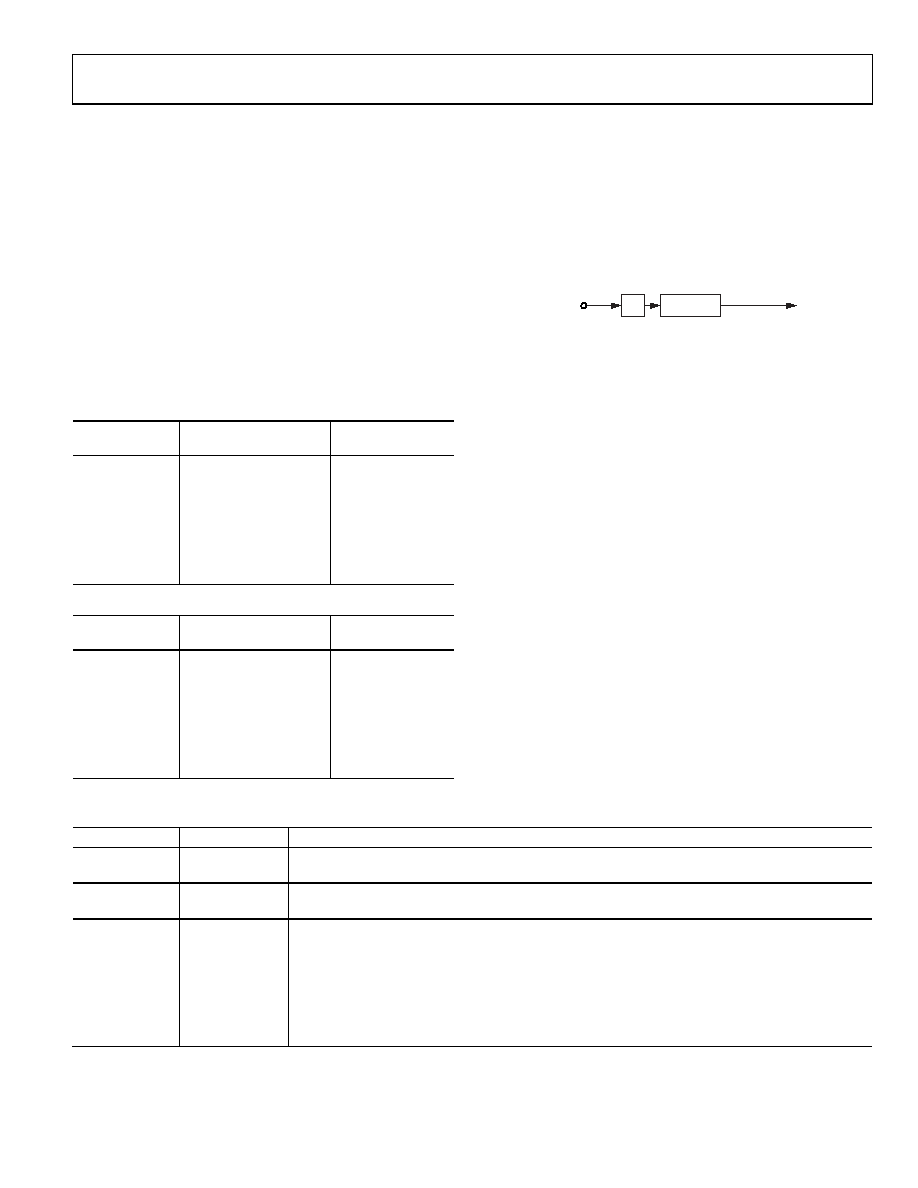
MCLK
÷ X
× (R + N/M)
TO PLL
CLOCK DIVIDER
089
14
-021
Figure 31. PLL Block Diagram
Integer Mode
Integer mode is used when the MCLK is an integer (R) multiple
of the PLL output (1024 × fS).
For example, if MCLK = 12.288 MHz and fS = 48 kHz, then
PLL required output = 1024 × 48 kHz = 49.152 MHz
R = 49.152 MHz/12.288 MHz = 4
In integer mode, the values set for N and M are ignored.
Fractional Mode
Fractional mode is used when the MCLK is a fractional
(R + (N/M)) multiple of the PLL output.
For example, if MCLK = 12 MHz and fS = 48 kHz, then
PLL required output = 1024 × 48 kHz = 49.152 MHz
R + (N/M) = 49.152 MHz/12 MHz = 4 + (12/125)
Common fractional PLL parameter settings for 44.1 kHz and
The PLL outputs a clock in the range of 41 MHz to 54 MHz,
which should be taken into account when calculating PLL
values and MCLK frequencies.
Table 14. PLL Control Register (Register R1, Address 0x4002)
Bits
Bit Name
Description
[47:32]
M[15:0]
Denominator of the fractional PLL: 16-bit binary number
0x00FD: M = 253 (default)
[31:16]
N[15:0]
Numerator of the fractional PLL: 16-bit binary number
0x000C: N = 12 (default)
[14:11]
R[3:0]
Integer part of PLL: four bits, only values 2 to 8 are valid
0010: R = 2 (default)
0011: R = 3
0100: R = 4
0101: R = 5
0110: R = 6
0111: R = 7
1000: R = 8
相关PDF资料 |
PDF描述 |
|---|---|
| SP3222EBCA-L/TR | IC TXRX RS232 ESD TRUE 20SSOP |
| AD7657BSTZ-REEL | IC ADC 14BIT 6CH 250KSPS 64-LQFP |
| LTC1867AIGN | IC ADC 16BIT 8CH 200KSPS 16SSOP |
| SP211EHCT-L/TR | IC TXRX RS232 MULTI-CH 28SOIC |
| CS44800-CQZR | IC AMP CTLR DGTL 8CH 64-LQFP |
相关代理商/技术参数 |
参数描述 |
|---|---|
| ADAU1462WBCPZ150 | 功能描述:32BIT SIGMADSP AUDIO 16K/48K 制造商:analog devices inc. 系列:* 包装:管件 零件状态:在售 安装类型:表面贴装 封装/外壳:72-VFQFN 裸露焊盘,CSP 供应商器件封装:72-LFCSP(10x10) 标准包装:1 |
| ADAU1462WBCPZ150RL | 功能描述:32BIT SIGMADSP AUDIO 16K/48K 制造商:analog devices inc. 系列:* 包装:带卷(TR) 零件状态:在售 安装类型:表面贴装 封装/外壳:72-VFQFN 裸露焊盘,CSP 供应商器件封装:72-LFCSP(10x10) 标准包装:2,000 |
| ADAU1462WBCPZ300 | 功能描述:32BIT SIGMADSP AUDIO 16K/48K 制造商:analog devices inc. 系列:* 包装:管件 零件状态:在售 安装类型:表面贴装 封装/外壳:72-VFQFN 裸露焊盘,CSP 供应商器件封装:72-LFCSP(10x10) 标准包装:1 |
| ADAU1462WBCPZ300RL | 功能描述:32BIT SIGMADSP AUDIO 16K/48K 制造商:analog devices inc. 系列:* 包装:带卷(TR) 零件状态:在售 安装类型:表面贴装 封装/外壳:72-VFQFN 裸露焊盘,CSP 供应商器件封装:72-LFCSP(10x10) 标准包装:2,000 |
| ADAU1463WBCPZ150 | 功能描述:32BIT SIGMADSP AUDIO 16K/48K 制造商:analog devices inc. 系列:* 包装:管件 零件状态:在售 安装类型:表面贴装 封装/外壳:72-VFQFN 裸露焊盘,CSP 供应商器件封装:72-LFCSP(10x10) 标准包装:1 |
发布紧急采购,3分钟左右您将得到回复。