- 您现在的位置:买卖IC网 > PDF目录378279 > ADC0851CIV (NATIONAL SEMICONDUCTOR CORP) 8-Bit Analog Data Acquisition and Monitoring Systems PDF资料下载
参数资料
| 型号: | ADC0851CIV |
| 厂商: | NATIONAL SEMICONDUCTOR CORP |
| 元件分类: | ADC |
| 英文描述: | 8-Bit Analog Data Acquisition and Monitoring Systems |
| 中文描述: | 2-CH 8-BIT SUCCESSIVE APPROXIMATION ADC, SERIAL ACCESS, PQCC20 |
| 封装: | PLASTIC, LCC-20 |
| 文件页数: | 23/36页 |
| 文件大小: | 581K |
| 代理商: | ADC0851CIV |
第1页第2页第3页第4页第5页第6页第7页第8页第9页第10页第11页第12页第13页第14页第15页第16页第17页第18页第19页第20页第21页第22页当前第23页第24页第25页第26页第27页第28页第29页第30页第31页第32页第33页第34页第35页第36页
3.0 Watchdog Mode
(Continued)
The device will read the new input word and configure to a
different mode if CS is high for less than eight oscillator
clock periods for the ADC0851 and less than thirty-two os-
cillator clock periods for the ADC0858.
Once a boundary limit is crossed, INT goes low. Moreover,
for ADC0851, COMPL goes low if a lower limit is crossed,
whereas COMPH goes low if an upper limit is crossed. If the
input signals exceed both the upper and lower boundary
limits then both COMPL and COMPH would go low.
To output data after a limit crossing occurs (i.e., after INT
goes low), CS should be brought low. Note that INT,
COMPL and COMPH would remain low as long as CS
doesn’t go low. After CS goes low INT, COMPL and
COMPH go high and one clock cycle later output data is
transmitted starting at the first rising edge of CLK, however,
the data is valid at the falling edge of CLK (Figure 7 ).
3.2 LIMIT CROSSING DETECTION
When the ADC0851/8 is configured in the watchdog mode,
the device operates as a window comparator. First the low-
er window limit (stored in the RAM) for CH0 is compared
against the input voltage at CH0. If the input voltage is
greater than the lower limit, then no interrupt is generated.
Next the upper window limit for CH0 is compared against
CH0 input voltage. If the input voltage is less than the upper
window limit then no interrupt is generated for CH0 and the
device starts a similar comparison cycle for the next chan-
nel (CH1). Note that the lower limit can be greater than the
upper limit; in this case the device will flag the microproces-
sor if the input signal falls inside a window.
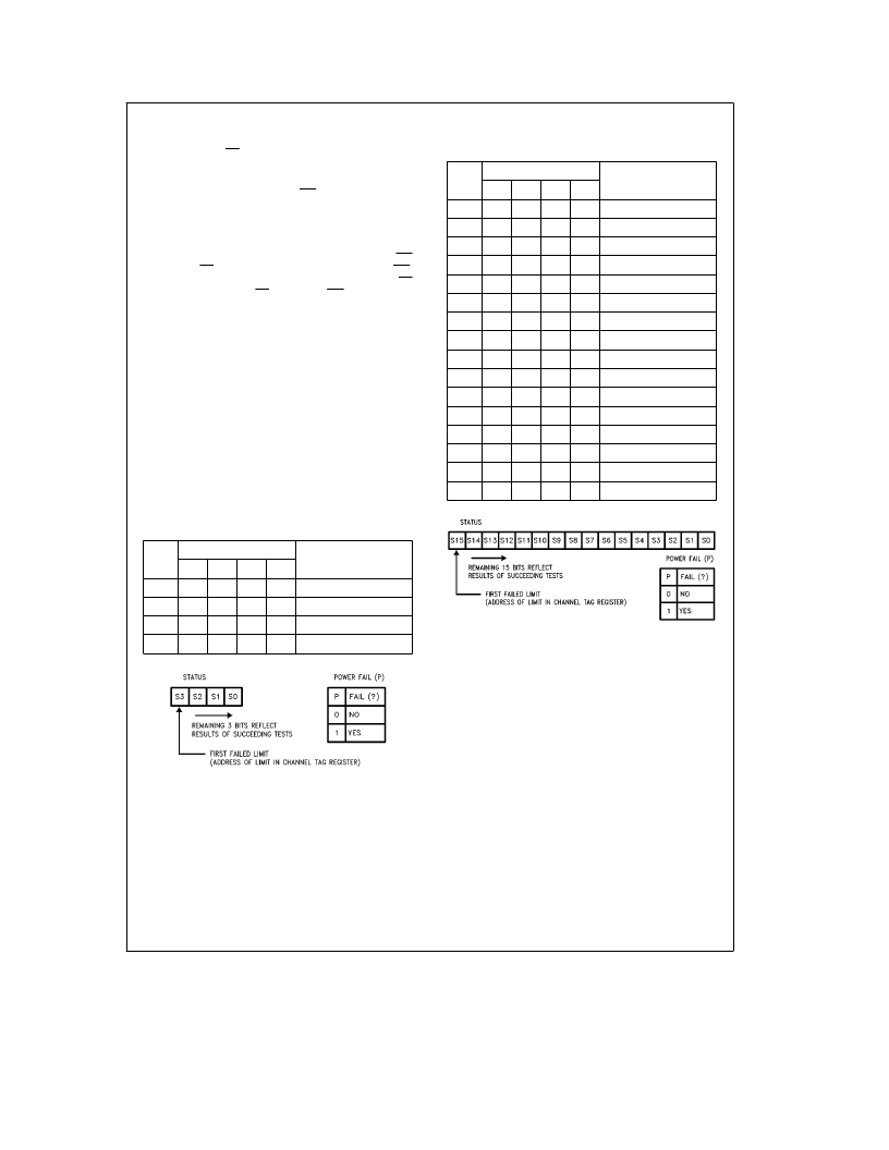
TABLE IVa. Channel Tag Address
and Status (ADC0851)
Tag
Y
Tag Address
Corresponding Limit
and Channel
T3
T2
T1
T0
0
0
0
0
0
Lower LimitDCH0
1
0
0
0
1
Upper LimitDCH0
2
0
0
1
0
Lower LimitDCH1
3
0
0
1
1
Upper LimitDCH1
TL/H/11021–43
TABLE IVb. Channel Tag Address
and Status (ADC0858)
Tag
Y
Tag Address
Corresponding Limit
and Channel
T3
T2
T1
T0
0
0
0
0
0
Lower LimitDCH0
1
0
0
0
1
Upper LimitDCH0
2
0
0
1
0
Lower LimitDCH1
3
0
0
1
1
Upper LimitDCH1
4
0
1
0
0
Lower LimitDCH2
5
0
1
0
1
Upper LimitDCH2
6
0
1
1
0
Lower LimitDCH3
7
0
1
1
1
Upper LimitDCH3
8
1
0
0
0
Lower LimitDCH4
9
1
0
0
1
Upper LimitDCH4
10
1
0
1
0
Lower LimitDCH5
11
1
0
1
1
Upper LimitDCH5
12
1
1
0
0
Lower LimitDCH6
13
1
1
0
1
Upper LimitDCH6
14
1
1
1
0
Lower LimitDCH7
15
1
1
1
1
Upper LimitDCH7
TL/H/11021–44
Each comparison takes 2
m
s; thus a total of 4
m
s is required
per channel.
When in watchdog mode, the device will continuously cycle
through the input channels until an input that has crossed its
preset window limit is detected. When this occurs, a logical
‘‘1’’ is stored in the MSB (bit S3 for ADC0851 and S15 for
ADC0858) position of the status register. In addition the tag
register is updated with the channel’s address (see Tables
IV(a) and (b) for ADC0851 and ADC0858 respectively). Note
that the tag address indicates which channel crossed which
limit. Once the tag register is updated after the first limit is
crossed, the device will once more cycle through the re-
maining channels and compare the input voltages against
23
相关PDF资料 |
PDF描述 |
|---|---|
| ADC0858CIN | 8-Bit Analog Data Acquisition and Monitoring Systems |
| ADC0858CIV | 8-Bit Analog Data Acquisition and Monitoring Systems |
| ADC0881 | 8-Bit 20 MSPS Flash A/D Converter |
| ADC0881CCC | 8-Bit 20 MSPS Flash A/D Converter |
| ADC0881CCJ | 8-Bit 20 MSPS Flash A/D Converter |
相关代理商/技术参数 |
参数描述 |
|---|---|
| ADC0851CMJ/883 | 制造商:未知厂家 制造商全称:未知厂家 功能描述:Single-Ended Data Acquisition System |
| ADC0852 | 制造商:NSC 制造商全称:National Semiconductor 功能描述:Multiplexed Comparator with 8-Bit Reference Divider |
| ADC0852BCJ/A+ | 制造商:未知厂家 制造商全称:未知厂家 功能描述:Analog Comparator |
| ADC0852BCN | 制造商:未知厂家 制造商全称:未知厂家 功能描述:Analog Comparator |
| ADC0852BCN/A+ | 制造商:未知厂家 制造商全称:未知厂家 功能描述:Analog Comparator |
发布紧急采购,3分钟左右您将得到回复。