- 您现在的位置:买卖IC网 > PDF目录97842 > ADL5504ACBZ-P2 (ANALOG DEVICES INC) 450 MHz - 6000 MHz RF/MICROWAVE LINEAR DETECTOR PDF资料下载
参数资料
| 型号: | ADL5504ACBZ-P2 |
| 厂商: | ANALOG DEVICES INC |
| 元件分类: | 检测器 |
| 英文描述: | 450 MHz - 6000 MHz RF/MICROWAVE LINEAR DETECTOR |
| 封装: | 1.20 X 0.80 MM, ROHS COMPLIANT, CB-6-8, WLCSP-6 |
| 文件页数: | 7/24页 |
| 文件大小: | 1156K |
| 代理商: | ADL5504ACBZ-P2 |
ADL5504
Rev. A | Page 15 of 24
Multiple RF Inputs
Figure 37 shows a technique for combining multiple RF input
signals to the ADL5504. Some applications can share a single
detector for multiple bands. Three 16.5 resistors in a T
network
combine the three 50 terminations (including the ADL5504
with the shunt 75 matching component). The broadband
resistive combiner ensures that each port of the T network sees
a 50 termination. Because there are only 6 dB of isolation
from one port of the combiner to the other ports, only one
band should be active at a time.
ADL5504
RFIN
BAND 1
50
BAND 2
DIRECTIONAL
COUPLER
16.5
50
16.5
16.5
DIRECTIONAL
COUPLER
75
08437-
037
Figure 37. Combining Multiple RF Input Signals
LINEARITY
Because the ADL5504 is a linear responding device, plots of output
voltage vs. input voltage result in a straight line (see Figure 4
and Figure 5) and the dynamic range in decibels (dB) is not
clearly visible. It is more useful to plot the error on a logarith-
mic scale, as shown in Figure 7. The deviation of the plot from
the ideal straight line characteristic is caused by input stage
clipping at the high end and by signal offsets at the low end.
However, offsets at the low end can be either positive or neg-
ative; therefore, the linearity error vs. input level plots (see
Figure 7) can also trend upwards at the low end. Figure 10 to
Figure 12 and Figure 16 to Figure 18 show error distributions
for a large population of devices at specific frequencies over
temperature.
It is also apparent in Figure 7 that the error at the lower portion
of the dynamic range tends to shift up as frequency is increased.
This is due to the calibration points chosen, 14 dBm and +8 dBm
(see the Device Calibration and Error Calculation section).
The absolute value cell has an input impedance that varies with
frequency. The result is a decrease in the actual voltage across the
squaring cell as the frequency increases, reducing the conversion
gain. The dynamic range is near constant over frequency, but
with a decrease in conversion gain as frequency is increased.
Output Swing
At 900 MHz, the VRMS output voltage is nominally 1.87× the
input rms voltage (a conversion gain of 1.87 V/V rms). The output
voltage swings from near ground to 2.5 V on a 3.0 V supply.
Figure 8 shows the output swings of the ADL5504 to a CW input
for various supply voltages. Only at the lowest supply voltage
(2.5 V) is there a reduction in the dynamic range as the input
headroom decreases.
Output Offset
The ADL5504 has a ±1 dB error detection range of about 30 dB,
The error is referred to the best-fit line defined in the linear
region of the output response (see the Device Calibration and
Error Calculation section for more details). Below an input
power of 18 dBm, the response is no longer linear and begins
to lose accuracy. In addition, depending on the supply voltage,
saturation may limit the detection accuracy above 12 dBm.
Calibration points should be chosen in the linear region,
avoiding the nonlinear ranges at the high and low extremes.
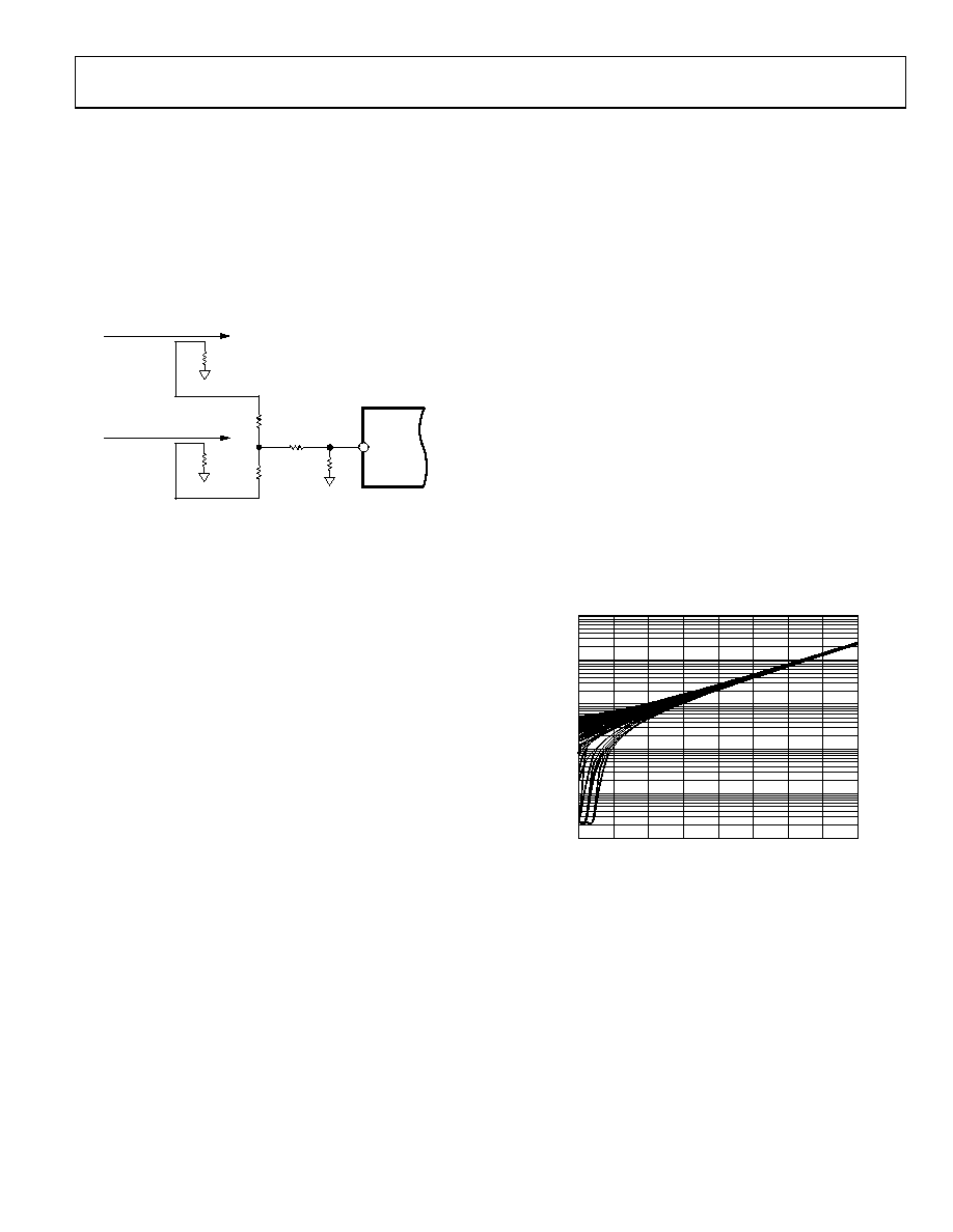
Figure 38 shows a distribution of the output response vs. the
input for multiple devices. The ADL5504 loses accuracy at low
input powers as the output response begins to fan out. As the
input power is reduced, the spread of the output response
increases along with the error.
10
0.0001
–25
15
INPUT (dBm)
O
U
T
PU
T
(V)
0.001
0.01
0.1
1
–20
–15
–10
–5
0
5
10
08437-
038
Figure 38. Output vs. Input Level Distribution of 50 Devices,
900 MHz Frequency, 3.0 V Supply
Although some devices follow the ideal linear response at very
low input powers, not all devices continue the ideal linear regres-
sion to a near 0 V y-intercept. Some devices exhibit output
responses that rapidly decrease and some flatten out.
With no RF signal applied, the ADL5504 has a typical output
offset of 10 mV (with a maximum of 100 mV) on VRMS.
相关PDF资料 |
PDF描述 |
|---|---|
| ADL5504ACBZ-P7 | 450 MHz - 6000 MHz RF/MICROWAVE LINEAR DETECTOR |
| ADL5535ARKZ-R7 | 20 MHz - 1000 MHz RF/MICROWAVE WIDE BAND LOW POWER AMPLIFIER |
| ADL5571 | 2500 MHz - 2700 MHz RF/MICROWAVE NARROW BAND MEDIUM POWER AMPLIFIER |
| ADRF6704ACPZ | 2500 MHz - 2900 MHz RF/MICROWAVE I/Q MODULATOR |
| AFEM-7780-BLK | 1920 MHz - 1980 MHz RF/MICROWAVE NARROW BAND MEDIUM POWER AMPLIFIER |
相关代理商/技术参数 |
参数描述 |
|---|---|
| ADL5504ACBZ-P7 | 功能描述:IC DETECTOR RF/IF TRUPWR 6WLCSP RoHS:是 类别:RF/IF 和 RFID >> RF 检测器 系列:TruPwr™ 产品变化通告:Product Discontinuation 15/May/2006 标准包装:3,000 系列:- 频率:100MHz ~ 2GHz RF 型:手机,GSM,DCS,PCS 输入范围:- 精确度:- 电源电压:2.7 V ~ 5.5 V 电流 - 电源:300µA 包装:带卷 (TR) 封装/外壳:SC-74,SOT-457 其它名称:NCS5000SNT1GOS |
| ADL5504-EVALZ | 制造商:Analog Devices 功能描述:EVALUATION BOARDS - Bulk |
| ADL5504XCBZ | 功能描述:IC DETECTOR RF TRUPWR 制造商:analog devices inc. 系列:* 零件状态:上次购买时间 标准包装:1 |
| ADL5505 | 制造商:AD 制造商全称:Analog Devices 功能描述:450 MHz to 6000Mhz TruPwr Detector |
| ADL5505ACBZ-P2 | 制造商:AD 制造商全称:Analog Devices 功能描述:450 MHz to 6000Mhz TruPwr Detector |
发布紧急采购,3分钟左右您将得到回复。