- 您现在的位置:买卖IC网 > PDF目录373995 > ADM1030 (Analog Devices, Inc.) Circular Connector; No. of Contacts:66; Series:LJT06R; Body Material:Aluminum; Connecting Termination:Crimp; Connector Shell Size:19; Circular Contact Gender:Socket; Circular Shell Style:Straight Plug; Insert Arrangement:19-35 PDF资料下载
参数资料
| 型号: | ADM1030 |
| 厂商: | Analog Devices, Inc. |
| 元件分类: | 圆形连接器 |
| 英文描述: | Circular Connector; No. of Contacts:66; Series:LJT06R; Body Material:Aluminum; Connecting Termination:Crimp; Connector Shell Size:19; Circular Contact Gender:Socket; Circular Shell Style:Straight Plug; Insert Arrangement:19-35 |
| 中文描述: | 智能温度监视器和PWM风扇控制器 |
| 文件页数: | 12/28页 |
| 文件大小: | 278K |
| 代理商: | ADM1030 |
第1页第2页第3页第4页第5页第6页第7页第8页第9页第10页第11页当前第12页第13页第14页第15页第16页第17页第18页第19页第20页第21页第22页第23页第24页第25页第26页第27页第28页
REV. 0
ADM1030
–12–
AUTOMATIC FAN SPEED CONTROL
The ADM1030 has a local temperature channel and a remote
temperature channel, which may be connected to an on-chip
diode-connected transistor on a CPU. These two temperature
channels may be used as the basis for an automatic fan speed
control loop to drive a fan using Pulsewidth Modulation (PWM).
HOW DOES THE CONTROL LOOP WORK
The Automatic Fan Speed Control Loop is shown in Fig-
ure 6 below.
FAN
SPEED
MAX
MIN
TEMPERATURE
T
MIN
T
MAX
= T
MIN
+ T
RANGE
SPIN UP FOR 2 SECONDS
Figure 6. Automatic Fan Speed Control
In order for the fan speed control loop to work, certain loop
parameters need to be programmed into the device.
1.
T
MIN
. The temperature at which the fan should switch on
and run at minimum speed. The fan will only turn on once
the temperature being measured rises above the T
MIN
value
programmed. The fan will spin up for a predetermined time
(default = 2 secs). See Fan Spin-Up section for more details.
2.
T
RANGE
. The temperature range over which the ADM1030
will automatically adjust the fan speed. As the temperature
increases beyond T
MIN
, the PWM_OUT duty cycle will be
increased accordingly. The T
RANGE
parameter actually defines
the fan speed versus temperature slope of the control loop.
3.
T
MAX
.
The temperature at which the fan will be at its maxi-
mum speed. At this temperature, the PWM duty cycle
driving the fan will be 100%. T
MAX
is given by T
MIN
+
T
RANGE
. Since this parameter is the sum of the T
MIN
and
T
RANGE
parameters, it does not need to be programmed into
a register on-chip.
4. A hysteresis value of 5
°
C is included in the control loop to
prevent the fan continuously switching on and off if the tem-
perature is close to T
MIN
. The fan will continue to run until
such time as the temperature drops 5
°
C below T
MIN
.
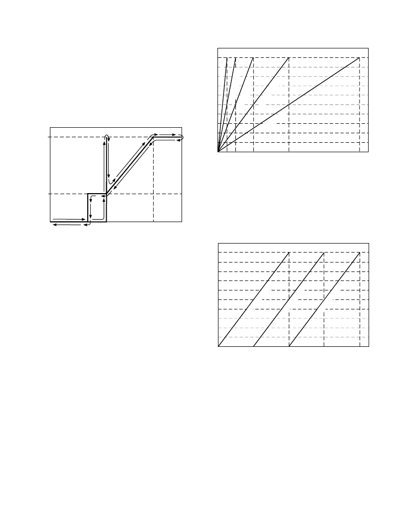
Figure 7 shows the different control slopes determined by the
T
RANGE
value chosen, and programmed into the ADM1030.
T
MIN
was set to 0
°
C to start all slopes from the same point. It
can be seen how changing the T
RANGE
value affects the PWM
duty cycle versus temperature slope.
TEMPERATURE
–
C
P
–
0
100
93
87
80
73
66
60
53
47
40
33
T
MIN
T
MAX
= T
MIN
+ T
RANGE
5
10
20
40
60
80
T
RANGE
=80 C
T
RANGE
0C
T
RNE
2C
T
RG
0
T
R
Figure 7. PWM Duty Cycle vs. Temperature Slopes (T
RANGE
)
Figure 8 shows how, for a given T
RANGE
, changing the T
MIN
value affects the loop. Increasing the T
MIN
value will increase
the T
MAX
(temperature at which the fan runs full speed) value,
since T
MAX
= T
MIN
+ T
RANGE
. Note, however, that the PWM
Duty Cycle vs Temperature slope remains exactly the same.
Changing the T
MIN
value merely shifts the control slope. The
T
MIN
may be changed in increments of 4
°
C.
TEMPERATURE
–
C
P
–
0
100
93
87
80
73
66
60
53
47
40
33
T
MIN
T
MAX
= T
MIN
+ T
RANGE
20
40
60
80
T
RANG
0C
T
RANGE
0C
T
RANG
0C
Figure 8. Effect of Increasing T
MIN
Value on Control Loop
FAN SPIN-UP
As was previously mentioned, once the temperature being mea-
sured exceeds the T
MIN
value programmed, the fan will turn on
at minimum speed (default = 33% duty cycle). However, the
problem with fans being driven by PWM is that 33% duty cycle
is not enough to reliably start the fan spinning. The solution is
to spin the fan up for a predetermined time, and once the fan
has spun up, its running speed may be reduced in line with the
temperature being measured.
The ADM1030 allows fan spin-up times between 200 ms and
8 seconds. Bits <2:0> of Fan Characteristics Register 1 (Register
0x20) program the fan spin-up time.
相关PDF资料 |
PDF描述 |
|---|---|
| ADM1033 | Thermal Monitor and Fan Speed (RPM) Controller |
| ADM1033ARQ | Thermal Monitor and Fan Speed (RPM) Controller |
| ADM1033ARQ-REEL | Thermal Monitor and Fan Speed (RPM) Controller |
| ADM1033ARQ-REEL7 | Thermal Monitor and Fan Speed (RPM) Controller |
| ADM1033ARQZ | Thermal Monitor and Fan Speed (RPM) Controller |
相关代理商/技术参数 |
参数描述 |
|---|---|
| ADM1030ARQ | 功能描述:IC SNSR TEMP/FAN PWM CTRL 16QSOP RoHS:否 类别:集成电路 (IC) >> PMIC - 热管理 系列:- 标准包装:1 系列:- 功能:温度监控系统(传感器) 传感器类型:内部和外部 感应温度:-40°C ~ 125°C,外部传感器 精确度:±2.5°C 本地(最大值),±5°C 远程(最大值) 拓扑:ADC,比较器,寄存器库 输出类型:2 线 SMBus? 输出警报:无 输出风扇:无 电源电压:2.7 V ~ 5.5 V 工作温度:-40°C ~ 125°C 安装类型:表面贴装 封装/外壳:SOT-23-8 供应商设备封装:SOT-23-8 包装:Digi-Reel® 其它名称:296-22675-6 |
| ADM1030ARQ-REEL | 功能描述:IC SNSR TEMP/FAN PWM CTRL 16QSOP RoHS:否 类别:集成电路 (IC) >> PMIC - 热管理 系列:- 标准包装:1 系列:- 功能:温度监控系统(传感器) 传感器类型:内部和外部 感应温度:-40°C ~ 125°C,外部传感器 精确度:±2.5°C 本地(最大值),±5°C 远程(最大值) 拓扑:ADC,比较器,寄存器库 输出类型:2 线 SMBus? 输出警报:无 输出风扇:无 电源电压:2.7 V ~ 5.5 V 工作温度:-40°C ~ 125°C 安装类型:表面贴装 封装/外壳:SOT-23-8 供应商设备封装:SOT-23-8 包装:Digi-Reel® 其它名称:296-22675-6 |
| ADM1030ARQ-REEL7 | 功能描述:IC SNSR TEMP/FAN PWM CTRL 16QSOP RoHS:否 类别:集成电路 (IC) >> PMIC - 热管理 系列:- 标准包装:1 系列:- 功能:温度监控系统(传感器) 传感器类型:内部和外部 感应温度:-40°C ~ 125°C,外部传感器 精确度:±2.5°C 本地(最大值),±5°C 远程(最大值) 拓扑:ADC,比较器,寄存器库 输出类型:2 线 SMBus? 输出警报:无 输出风扇:无 电源电压:2.7 V ~ 5.5 V 工作温度:-40°C ~ 125°C 安装类型:表面贴装 封装/外壳:SOT-23-8 供应商设备封装:SOT-23-8 包装:Digi-Reel® 其它名称:296-22675-6 |
| ADM1030ARQZ | 功能描述:马达/运动/点火控制器和驱动器 TDM & PWM FAN CNTRLRS IC RoHS:否 制造商:STMicroelectronics 产品:Stepper Motor Controllers / Drivers 类型:2 Phase Stepper Motor Driver 工作电源电压:8 V to 45 V 电源电流:0.5 mA 工作温度:- 25 C to + 125 C 安装风格:SMD/SMT 封装 / 箱体:HTSSOP-28 封装:Tube |
| ADM1030ARQZ-REEL | 功能描述:板上安装温度传感器 TDM PWM FAN CTRLRS IC RoHS:否 制造商:Omron Electronics 输出类型:Digital 配置: 准确性:+/- 1.5 C, +/- 3 C 温度阈值: 数字输出 - 总线接口:2-Wire, I2C, SMBus 电源电压-最大:5.5 V 电源电压-最小:4.5 V 最大工作温度:+ 50 C 最小工作温度:0 C 关闭: 安装风格: 封装 / 箱体: 设备功能:Temperature and Humidity Sensor |
发布紧急采购,3分钟左右您将得到回复。