参数资料
| 型号: | ADM2682EBRIZ |
| 厂商: | Analog Devices Inc |
| 文件页数: | 18/24页 |
| 文件大小: | 0K |
| 描述: | IC ISOLATOR DIGITAL 16-SOIC |
| 视频文件: | ADM2682E / ADM2687E 5kVrms Signal & Power Isolated RS-485 Transceivers |
| 标准包装: | 37 |
| 系列: | isoPower® |
| 类型: | 收发器 |
| 电压 - 隔离: | 5000Vrms |
| 输入类型: | DC |
| 电源电压: | 3.3V |
| 工作温度: | -40°C ~ 85°C |
| 安装类型: | 表面贴装 |
| 封装/外壳: | 16-SOIC(0.295",7.50mm 宽) |
| 供应商设备封装: | 16-SOIC-IC |
| 包装: | 管件 |
�� ��
��
��ADM2682E/ADM2687E�
�APPLICATIONS� INFORMATION�
�PCB� LAYOUT�
�The� ADM2682E� /� ADM2687E� isolated� RS-422/RS-485� transceiver�
�contains� an� iso� Power� integrated� dc-to-dc� converter,� requiring�
�no� external� interface� circuitry� for� the� logic� interfaces.� Power�
�supply� bypassing� is� required� at� the� input� and� output� supply� pins�
��ADM2687E� uses� an� 180� MHz� oscillator� frequency� to� pass� power�
�efficiently� through� its� chip-scale� transformers.� In� addition,� the�
�normal� operation� of� the� data� section� of� the� i� Coupler� introduces�
�switching� transients� on� the� power� supply� pins.�
�Bypass� capacitors� are� required� for� several� operating� frequencies.�
�Noise� suppression� requires� a� low� inductance,� high� frequency�
�capacitor,� whereas� ripple� suppression� and� proper� regulation�
�require� a� large� value� capacitor.� These� capacitors� are� connected�
�between� Pin� 1� (GND� 1� )� and� Pin� 2� (V� CC� )� and� Pin� 7� (V� CC� )� and�
�Pin� 8� (GND� 1� )� for� V� CC� .� The� V� ISOIN� and� V� ISOOUT� capacitors� are�
�connected� between� Pin� 9� (GND� 2� )� and� Pin� 10� (V� ISOOUT� )� and�
�Pin� 15� (V� ISOIN� )� and� Pin� 16� (GND� 2� ).� To� suppress� noise� and� reduce�
�ripple,� a� parallel� combination� of� at� least� two� capacitors� is� required�
�with� the� smaller� of� the� two� capacitors� located� closest� to� the� device.�
�The� recommended� capacitor� values� are� 0.1� μF� and� 10� μF� for�
�V� ISOOUT� at� Pin� 9� and� Pin� 10� and� V� CC� at� Pin� 7� and� Pin� 8.� Capacitor�
�values� of� 0.01� μF� and� 0.1� μF� are� recommended� for� V� ISOIN� at� Pin� 15�
�and� Pin� 16� and� V� CC� at� Pin� 1� and� Pin� 2.� The� recommended� best�
�practice� is� to� use� a� very� low� inductance� ceramic� capacitor,� or� its�
�equivalent,� for� the� smaller� value� capacitors.� The� total� lead� length�
�between� both� ends� of� the� capacitor� and� the� input� power� supply�
�pin� should� not� exceed� 10� mm.�
�Data� Sheet�
�In� applications� involving� high� common-mode� transients,� ensure�
�that� board� coupling� across� the� isolation� barrier� is� minimized.�
�Furthermore,� design� the� board� layout� such� that� any� coupling�
�that� does� occur� equally� affects� all� pins� on� a� given� component�
�side.� Failure� to� ensure� this� can� cause� voltage� differentials� between�
�pins� exceeding� the� absolute� maximum� ratings� for� the� device,�
�thereby� leading� to� latch-up� and/or� permanent� damage.�
�The� ADM2682E� /� ADM2687E� dissipate� approximately� 675� mW�
�of� power� when� fully� loaded.� Because� it� is� not� possible� to� apply�
�a� heat� sink� to� an� isolation� device,� the� devices� primarily� depend�
�on� heat� dissipation� into� the� PCB� through� the� GND� pins.� If� the�
�devices� are� used� at� high� ambient� temperatures,� provide� a� thermal�
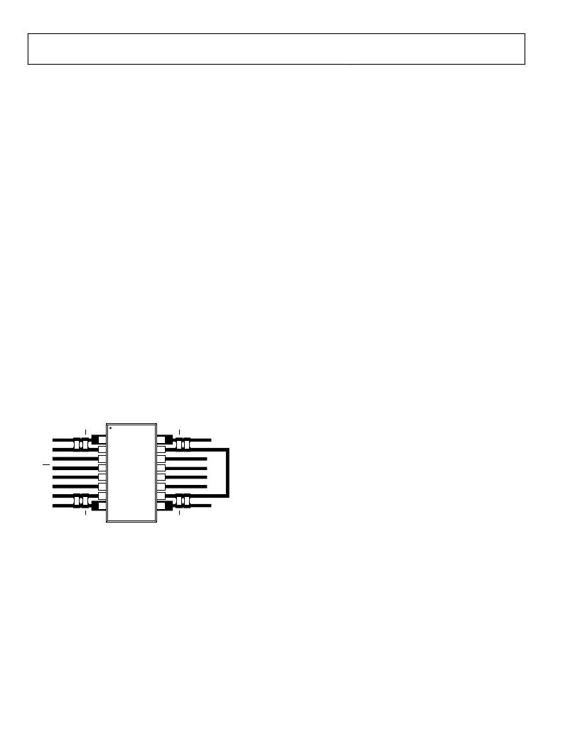
�path� from� the� GND� pins� to� the� PCB� ground� plane.� The� board�
�layout� in� Figure� 41� shows� enlarged� pads� for� Pin� 1,� Pin� 8,� Pin� 9,�
�and� Pin� 16.� Implement� multiple� vias� from� the� pad� to� the� ground�
�plane� to� reduce� the� temperature� inside� the� chip� significantly.� The�
�dimensions� of� the� expanded� pads� are� at� the� discretion� of� the�
�designer� and� dependent� on� the� available� board� space.�
�EMI� CONSIDERATIONS�
��components� must,� of� necessity,� operate� at� very� high� frequency�
�to� allow� efficient� power� transfer� through� the� small� transformers.�
�This� creates� high� frequency� currents� that� can� propagate� in� circuit�
�board� ground� and� power� planes,� causing� edge� and� dipole� radiation.�
�Grounded� enclosures� are� recommended� for� applications� that�
�use� these� devices.� If� grounded� enclosures� are� not� possible,� good�
�RF� design� practices� should� be� followed� in� the� layout� of� the� PCB.�
�See� the� AN-0971� Application� Note� ,� Recommendations� for� Control�
�10nF�
�100nF�
�10nF�
�100nF�
�of� Radiated� Emissions� with� isoPower� Devices� ,� for� more� information.�
�GND� 1�
�V� CC�
�1�
�2�
�16�
�15�
�GND� 2�
�V� ISOIN�
�RxD�
�RE�
�DE�
�TxD�
�V� CC�
�GND� 1�
�3�
�4�
�5�
�6�
�7�
�8�
�ADM2682E/�
�ADM2687E�
�14�
�13�
�12�
�11�
�10�
�9�
�A�
�B�
�Z�
�Y�
�GND� 2�
�V� ISOOUT�
�10μF�
�100nF�
�10μF�
�100nF�
�Figure� 41.� Recommended� PCB� Layout�
�Rev.� B� |� Page� 18� of� 24�
�相关PDF资料 |
PDF描述 |
|---|---|
| ADM2914-1SRQZEP | IC VOLT SUP QUAD UV/OV 16QSOP |
| ADM6306D344ARJZ-R7 | IC SUPERVISOR DUAL SOT23-5 |
| ADM6315-26D2ARTRL7 | IC SUPERVISOR OD 2.63V SOT143 |
| ADM6318CY45ARJZ-R7 | IC SUPERVISOR WATCHDOG SOT23-5 |
| ADM6339LARJZ-RL7 | IC MCU SUP ADJ/33/25/ADJ SOT23-6 |
相关代理商/技术参数 |
参数描述 |
|---|---|
| ADM2682EBRIZ-RL | 制造商:Analog Devices 功能描述: |
| ADM2682EBRIZ-RL7 | 功能描述:IC TXRX ISOLATED RS485 16SOIC RoHS:是 类别:隔离器 >> 专用型 系列:isoPower® 标准包装:50 系列:- 类型:晶体管反相器 电压 - 隔离:2500Vrms 输入类型:DC 电源电压:5 V ~ 13 V 工作温度:-30°C ~ 70°C 安装类型:通孔 封装/外壳:8-DIP(0.300",7.62mm) 供应商设备封装:8-DIP 包装:管件 |
| ADM2687E | 制造商:AD 制造商全称:Analog Devices 功能描述:5 kV rms Signal and Power Isolated |
| ADM2687EBRIZ | 功能描述:IC TRXR ISOLATED RS-485 16-SOIC RoHS:是 类别:隔离器 >> 专用型 系列:isoPower® 标准包装:50 系列:- 类型:晶体管反相器 电压 - 隔离:2500Vrms 输入类型:DC 电源电压:5 V ~ 13 V 工作温度:-30°C ~ 70°C 安装类型:通孔 封装/外壳:8-DIP(0.300",7.62mm) 供应商设备封装:8-DIP 包装:管件 |
| ADM2687EBRIZ-RL7 | 功能描述:IC TXRX ISOLATED RS485 16SOIC RoHS:是 类别:隔离器 >> 专用型 系列:isoPower® 标准包装:50 系列:- 类型:晶体管反相器 电压 - 隔离:2500Vrms 输入类型:DC 电源电压:5 V ~ 13 V 工作温度:-30°C ~ 70°C 安装类型:通孔 封装/外壳:8-DIP(0.300",7.62mm) 供应商设备封装:8-DIP 包装:管件 |
发布紧急采购,3分钟左右您将得到回复。