- 您现在的位置:买卖IC网 > PDF目录1898 > ADM3053BRWZ-REEL7 (Analog Devices Inc)IC TXRX ISOLATED CAN 20SOIC PDF资料下载
参数资料
| 型号: | ADM3053BRWZ-REEL7 |
| 厂商: | Analog Devices Inc |
| 文件页数: | 6/20页 |
| 文件大小: | 0K |
| 描述: | IC TXRX ISOLATED CAN 20SOIC |
| 产品培训模块: | iCoupler Digital Isolater Technology |
| 标准包装: | 400 |
| 系列: | IsoPower®, iCoupler® |
| 类型: | 收发器 |
| 驱动器/接收器数: | 1/1 |
| 规程: | CAN |
| 电源电压: | 3.3V,5V |
| 安装类型: | 表面贴装 |
| 封装/外壳: | 20-SOIC(0.295",7.50mm 宽) |
| 供应商设备封装: | 20-SOIC W |
| 包装: | 带卷 (TR) |
ADM3053
Data Sheet
Rev. B | Page 14 of 20
winding. At the secondary winding, the induced waveforms are
decoded into the binary value that was originally transmitted.
Positive and negative logic transitions at the isolator input cause
narrow (~1 ns) pulses to be sent to the decoder via the transformer.
The decoder is bistable and is, therefore, either set or reset by
the pulses, indicating input logic transitions. In the absence of
logic transitions at the input for more than 1 s, periodic sets of
refresh pulses indicative of the correct input state are sent to
ensure dc correctness at the output. If the decoder receives no
internal pulses of more than approximately 5 μs, the input side
is assumed to be unpowered or nonfunctional, in which case,
the isolator output is forced to a default state by the watchdog
timer circuit.
This situation should occur in the ADM3053 devices only during
power-up and power-down operations. The limitation on the
ADM3053 magnetic field immunity is set by the condition in
which induced voltage in the transformer receiving coil is
sufficiently large to either falsely set or reset the decoder. The
following analysis defines the conditions under which this
can occur.
The 3.3 V operating condition of the ADM3053 is examined
because it represents the most susceptible mode of operation.
The pulses at the transformer output have an amplitude of >1.0 V.
The decoder has a sensing threshold of about 0.5 V, thus
establishing a 0.5 V margin in which induced voltages can be
tolerated. The voltage induced across the receiving coil is
given by
V = (dβ/dt)Σπrn2; n = 1, 2, … , N
where:
β is magnetic flux density (gauss).
N is the number of turns in the receiving coil.
rn is the radius of the nth turn in the receiving coil (cm).
Given the geometry of the receiving coil in the ADM3053 and
an imposed requirement that the induced voltage be, at most,
50% of the 0.5 V margin at the decoder, a maximum allowable
magnetic field is calculated as shown in Figure 26.
MAGNETIC FIELD FREQUENCY (Hz)
100
M
A
X
IM
U
M
A
LLOWA
B
LE
M
A
GN
E
TIC
FLU
X
DE
NS
IT
Y
(
kg
au
ss)
0.001
1M
10
0.01
1k
10k
10M
0.1
1
100M
100k
09293-
010
Figure 26. Maximum Allowable External Magnetic Flux Density
For example, at a magnetic field frequency of 1 MHz, the
maximum allowable magnetic field of 0.2 kgauss induces a
voltage of 0.25 V at the receiving coil. This is about 50% of the
sensing threshold and does not cause a faulty output transition.
Similarly, if such an event occurs during a transmitted pulse
(and is of the worst-case polarity), it reduces the received pulse
from >1.0 V to 0.75 V, which is still well above the 0.5 V sensing
threshold of the decoder.
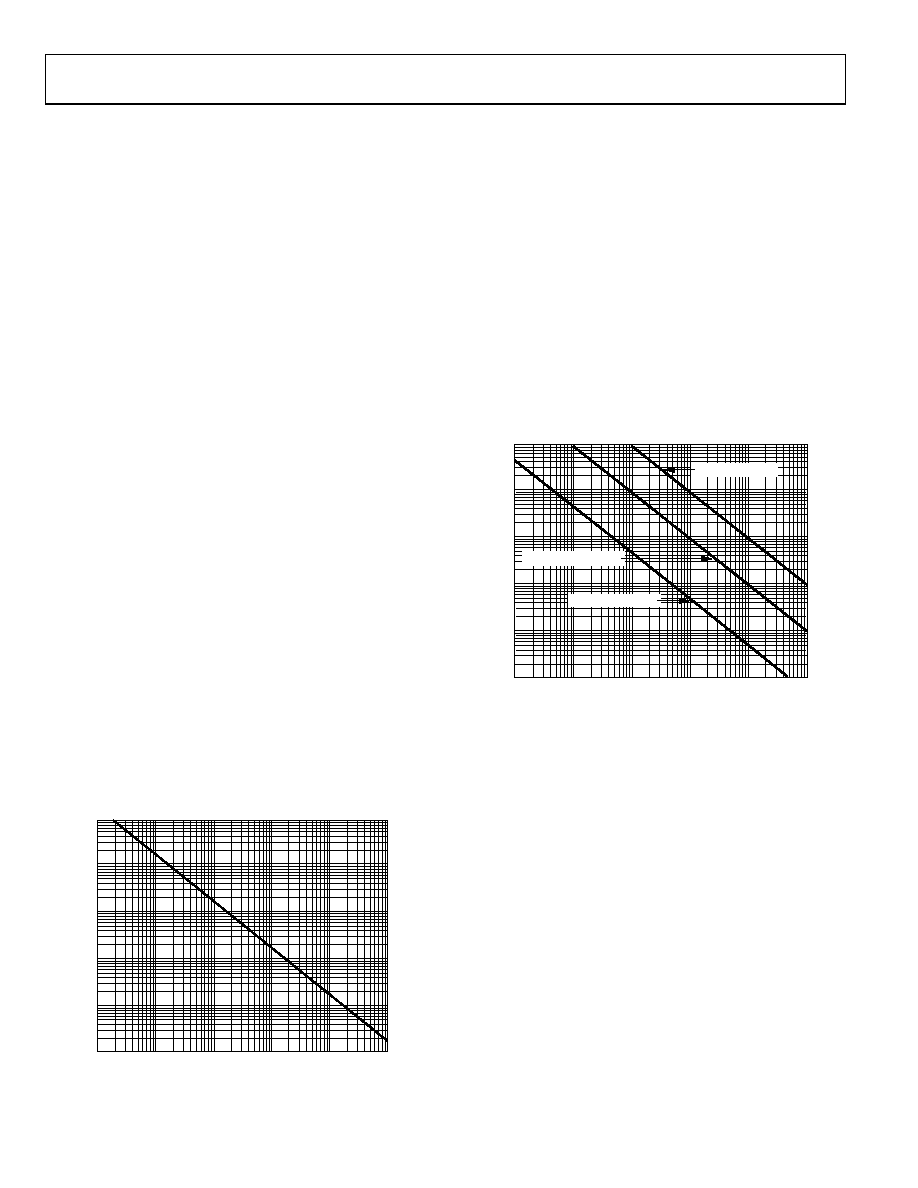
The preceding magnetic flux density values correspond
to specific current magnitudes at given distances from the
ADM3053 transformers. Figure 27 expresses these allowable
current magnitudes as a function of frequency for selected
distances. As shown in Figure 27, the ADM3053 is extremely
immune and can be affected only by extremely large currents
operated at high frequency very close to the component. For the
1 MHz example, a 0.5 kA current must be placed 5 mm away from
the ADM3053 to affect component operation.
MAGNETIC FIELD FREQUENCY (Hz)
M
AX
IM
UM
AL
L
O
W
ABL
E
CURRE
NT
(
kA)
1k
100
10
1
0.1
0.01
1k
10k
100M
100k
1M
10M
DISTANCE = 5mm
DISTANCE = 1m
DISTANCE = 100mm
09293-
0
1
Figure 27. Maximum Allowable Current for Various Current-to-ADM3053
Spacings
Note that in combinations of strong magnetic field and high
frequency, any loops formed by the printed circuit board (PCB)
traces can induce error voltages sufficiently large to trigger the
thresholds of succeeding circuitry. Proceed with caution in the
layout of such traces to prevent this from occurring.
相关PDF资料 |
PDF描述 |
|---|---|
| ADM3054BRWZ-RL7 | IC TXRX CAN HS 16SOIC |
| ADM3071EARZ | IC TXRX RS-485 3.3V FD 8-SOIC |
| ADM3101EARQZ-REEL | IC TXRX RS-232 3.3V 15KV 16QSOP |
| ADM3232EARWZ | IC RCVR/LINEDRIVER RS232 16SOIC |
| ADM3251EARWZ | IC TXRX RS232 ISOLATED 20-SOIC |
相关代理商/技术参数 |
参数描述 |
|---|---|
| ADM3054 | 制造商:Analog Devices 功能描述:IC CAN TRANSCEIVER 1MBPS 16SOIC 制造商:Analog Devices 功能描述:IC, CAN, TRANSCEIVER, 1MBPS, 16SOIC 制造商:Analog Devices 功能描述:IC, CAN, TRANSCEIVER, 1MBPS, 16SOIC; Interface Type:CAN; No. of TX Buffers:1; No. of RX Buffers:1; Supply Voltage Min:3V; Supply Voltage Max:5.5V; Digital IC Case Style:SOIC; No. of Pins:16; Operating Temperature Min:-40C; Operating;RoHS Compliant: Yes |
| ADM3054BRWZ | 功能描述:IC TRANSCEIVER CAN 16SOIC RoHS:是 类别:集成电路 (IC) >> 接口 - 驱动器,接收器,收发器 系列:* 产品培训模块:RS-232 & USB Transceiver 标准包装:2,000 系列:- 类型:收发器 驱动器/接收器数:1/1 规程:RS232 电源电压:3 V ~ 5.5 V 安装类型:表面贴装 封装/外壳:16-SSOP(0.209",5.30mm 宽) 供应商设备封装:16-SSOP 包装:带卷 (TR) 其它名称:296-19849-2 |
| ADM3054BRWZ | 制造商:Analog Devices 功能描述:IC Interface Type:- No. of TX Buffers |
| ADM3054BRWZ-RL7 | 功能描述:IC TXRX CAN HS 16SOIC RoHS:是 类别:集成电路 (IC) >> 接口 - 驱动器,接收器,收发器 系列:* 标准包装:27 系列:- 类型:收发器 驱动器/接收器数:3/3 规程:RS232,RS485 电源电压:4.75 V ~ 5.25 V 安装类型:表面贴装 封装/外壳:28-SOIC(0.295",7.50mm 宽) 供应商设备封装:28-SOIC 包装:管件 |
| ADM3054WBRWZ-RL7 | 功能描述:CAN Digital Isolator 5000Vrms 3 Channel 1Mbps 25kV/μs CMTI 16-SOIC (0.295", 7.50mm Width) 制造商:analog devices inc. 系列:iCoupler? 包装:剪切带(CT) 零件状态:有效 技术:磁耦合 类型:CAN 隔离式电源:无 通道数:3 输入 - 输入侧 1/输入侧 2:1/2 通道类型:单向 电压 - 隔离:5000Vrms 共模瞬态抗扰度(最小值):25kV/μs 数据速率:1Mbps 传播延迟 tpLH / tpHL(最大值):- 脉宽失真(最大):- 上升/下降时间(典型值):- 电压 - 电源:3.3V,5V 工作温度:-40°C ~ 125°C 封装/外壳:16-SOIC(0.295",7.50mm 宽) 供应商器件封装:16-SOIC 标准包装:1 |
发布紧急采购,3分钟左右您将得到回复。