- 您现在的位置:买卖IC网 > PDF目录375259 > ADM489 (Analog Devices, Inc.) Full-Duplex, Low Power,Slew Rate Limited, EIA RS-486 Transceivers(低功耗,全双工,转换速率限制,RS-485收发器) PDF资料下载
参数资料
| 型号: | ADM489 |
| 厂商: | Analog Devices, Inc. |
| 英文描述: | Full-Duplex, Low Power,Slew Rate Limited, EIA RS-486 Transceivers(低功耗,全双工,转换速率限制,RS-485收发器) |
| 中文描述: | 全双工,低功耗,限摆率限制,环境影响评估的RS - 486收发器(低功耗,全双工,转换速率限制,RS - 485接口收发器) |
| 文件页数: | 9/12页 |
| 文件大小: | 179K |
| 代理商: | ADM489 |
ADM488/ADM489
–9–
REV. 0
T he fast transient burst test, defined in IEC1000-4-4, simulates
this arcing and its waveform is illustrated in Figure 20. It
consists of a burst of 2.5 kHz to 5 kHz transients repeating at
300 ms intervals. It is specified for both power and data lines.
Four severity levels are defined in terms of an open-circuit volt-
age as a function of installation environment. T he installation
environments are defined as
1. Well-protected
2. Protected
3. T ypical Industrial
4. Severe Industrial
300ms
16ms
V
t
V
0.2/0.4ms
t
5ns
50ns
Figure 20. IEC1000-4-4 Fast Transient Waveform
T able III shows the peak voltages for each of the environments.
T able III.
V
PE AK
(kV)
PSU
V
PE AK
(kV)
I-O
Level
1
2
3
4
0.5
1
2
4
0.25
0.5
1
2
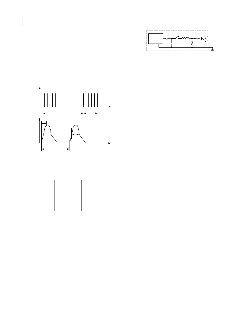
A simplified circuit diagram of the actual EFT generator is
illustrated in Figure 21.
T hese transients are coupled onto the signal lines using an EFT
coupling clamp. T he clamp is 1 m long and completely sur-
rounds the cable, providing maximum coupling capacitance
(50 pF to 200 pF typ) between the clamp and the cable. High
energy transients are capacitively coupled onto the signal lines.
Fast rise times (5 ns) as specified by the standard result in very
effective coupling. T his test is very severe since high voltages are
coupled onto the signal lines. T he repetitive transients can often
cause problems, where single pulses do not. Destructive latchup
may be induced due to the high energy content of the transients.
Note that this stress is applied while the interface products are
powered up and are transmitting data. T he EFT test applies
hundreds of pulses with higher energy than ESD. Worst case
transient current on an I-O line can be as high as 40 A.
HIGH
VOLTAGE
SOURCE
R
C
C
C
Z
S
L
R
M
C
D
50
V
OUTPUT
Figure 21. EFT Generator
T est results are classified according to the following:
1. Normal performance within specification limits.
2. T emporary degradation or loss of performance that is self-
recoverable.
3. T emporary degradation or loss of function or performance
that requires operator intervention or system reset.
4. Degradation or loss of function that is not recoverable due to
damage.
T he ADM488/ADM489 has been tested under worst case con-
ditions using unshielded cables, and meets Classification 2 at
severity Level 4. Data transmission during the transient condi-
tion is corrupted, but it may be resumed immediately following
the EFT event without user intervention.
RADIAT E D IMMUNIT Y (IE C1000-4-3)
IEC1000-4-3 (previously IEC801-3) describes the measurement
method and defines the levels of immunity to radiated electro-
magnetic fields. It was originally intended to simulate the elec-
tromagnetic fields generated by portable radio transceivers or
any other device that generates continuous wave radiated electro-
magnetic energy. Its scope has since been broadened to include
spurious EM energy, which can be radiated from fluorescent
lights, thyristor drives, inductive loads, etc.
T esting for immunity involves irradiating the device with an EM
field. T here are various methods of achieving this including use
of anechoic chamber, stripline cell, T EM cell and GT EM cell.
T hese consist essentially of two parallel plates with an electric
field developed between them. T he device under test is placed
between the plates and exposed to the electric field. T here are
three severity levels having field strengths ranging from 1 V to
10 V/m. Results are classified as follows:
1. Normal Operation.
2. T emporary Degradation or loss of function that is self-
recoverable when the interfering signal is removed.
3. T emporary degradation or loss of function that requires
operator intervention or system reset when the interfering
signal is removed.
4. Degradation or loss of function that is not recoverable due to
damage.
相关PDF资料 |
PDF描述 |
|---|---|
| ADM560JR | Ultralow Power, +3.3 V, RS-232 Notebook PC Serial Port Drivers/Receivers |
| ADM560JRS | Ultralow Power, +3.3 V, RS-232 Notebook PC Serial Port Drivers/Receivers |
| ADM561 | Ultralow Power, +3.3 V, RS-232 Notebook PC Serial Port Drivers/Receivers |
| ADM561JR | Ultralow Power, +3.3 V, RS-232 Notebook PC Serial Port Drivers/Receivers |
| ADM561JRS | Ultralow Power, +3.3 V, RS-232 Notebook PC Serial Port Drivers/Receivers |
相关代理商/技术参数 |
参数描述 |
|---|---|
| ADM489A | 制造商:AD 制造商全称:Analog Devices 功能描述:Full-Duplex, Low Power, Slew Rate Limited, EIA RS-485 Transceivers |
| ADM489ABRMZ | 功能描述:IC TXRX RS485/422 DIFF 10MSOP RoHS:是 类别:集成电路 (IC) >> 接口 - 驱动器,接收器,收发器 系列:- 标准包装:121 系列:- 类型:收发器 驱动器/接收器数:1/1 规程:RS422,RS485 电源电压:3 V ~ 3.6 V 安装类型:表面贴装 封装/外壳:10-WFDFN 裸露焊盘 供应商设备封装:10-DFN(3x3) 包装:管件 |
| ADM489ABRMZ-REEL7 | 功能描述:IC TXRX RS485/422 DIFF 10MSOP RoHS:是 类别:集成电路 (IC) >> 接口 - 驱动器,接收器,收发器 系列:- 标准包装:121 系列:- 类型:收发器 驱动器/接收器数:1/1 规程:RS422,RS485 电源电压:3 V ~ 3.6 V 安装类型:表面贴装 封装/外壳:10-WFDFN 裸露焊盘 供应商设备封装:10-DFN(3x3) 包装:管件 |
| ADM489ABRZ | 功能描述:IC TXRX RS485/422 DIFF 14SOIC RoHS:是 类别:集成电路 (IC) >> 接口 - 驱动器,接收器,收发器 系列:- 标准包装:121 系列:- 类型:收发器 驱动器/接收器数:1/1 规程:RS422,RS485 电源电压:3 V ~ 3.6 V 安装类型:表面贴装 封装/外壳:10-WFDFN 裸露焊盘 供应商设备封装:10-DFN(3x3) 包装:管件 |
| ADM489ABRZ-REEL7 | 功能描述:IC TXRX RS485/422 DIFF 14SOIC RoHS:是 类别:集成电路 (IC) >> 接口 - 驱动器,接收器,收发器 系列:- 标准包装:121 系列:- 类型:收发器 驱动器/接收器数:1/1 规程:RS422,RS485 电源电压:3 V ~ 3.6 V 安装类型:表面贴装 封装/外壳:10-WFDFN 裸露焊盘 供应商设备封装:10-DFN(3x3) 包装:管件 |
发布紧急采购,3分钟左右您将得到回复。