- 您现在的位置:买卖IC网 > PDF目录375259 > ADM561 (Analog Devices, Inc.) Ultralow Power, +3.3 V, RS-232 Notebook PC Serial Port Drivers/Receivers PDF资料下载
参数资料
| 型号: | ADM561 |
| 厂商: | Analog Devices, Inc. |
| 英文描述: | Ultralow Power, +3.3 V, RS-232 Notebook PC Serial Port Drivers/Receivers |
| 中文描述: | 超低功耗,3.3伏特和RS - 232串口笔记本电脑驱动器/接收器 |
| 文件页数: | 2/6页 |
| 文件大小: | 246K |
| 代理商: | ADM561 |
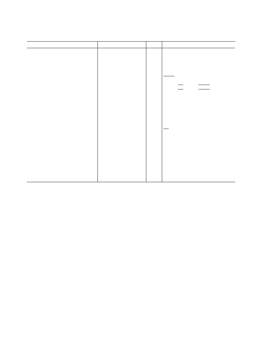
Parameter
Min
Typ
Max
Units
Test Conditions/Comments
Output Voltage Swing
±
5.0
±
5.5
Volts
V
CC
= 3.3 V, Three Transmitter Outputs
Loaded with 3 k
to Ground
V
CC
= 3.0 V, All Transmitter Outputs
Loaded into 3 k
to Ground
No Load, T
IN
= V
CC
No Load,T
IN
= GND
SHDN
= GND (ADM560); SHDN
= V
CC
(ADM561), T
IN
= V
CC
T
IN,
EN,
EN
, SHDN,
SHDN
,
T
IN,
EN,
EN
, SHDN,
SHDN
T
IN
= GND
±
4
±
4.5
Volts
V
CC
Power Supply Current
1.3
2.2
0.2
2
3.0
5
mA
mA
μ
A
Shutdown Supply Current
Input Logic Threshold Low, V
INL
Input Logic Threshold High, V
INH
Logic Pullup Current
EIA-232 Input Voltage Range
EIA-232 Input Threshold Low
EIA-232 Input Threshold High
EIA-232 Input Hysteresis
EIA-232 Input Resistance
CMOS Output Voltage Low, V
OL
CMOS Output Voltage High, V
OH
CMOS Output Leakage Current
Output Enable Time
Output Disable Time
Receiver Propagation Delay
TPHL
TPLH
Instantaneous Slew Rate
Transition Region Slew Rate
0.4
V
V
μ
A
V
V
V
V
k
V
V
μ
A
ns
ns
2.4
3
20
+25
–25
0.4
0.8
1.1
0.3
5
2.4
3
7
0.4
I
OUT
= 1.6 mA
I
OUT
= –40
μ
A
EN
= V
CC
, EN = GND, 0 V
≤
R
OUT
≤
V
CC
2.8
0.05
200
300
±
5
0.4
1.3
1
2
30
μ
s
μ
s
V/
μ
s
V/
μ
s
C
L
= 50 pF, R
L
= 3 k
–7 k
R
L
= 3 k
, C
L
= 2500 pF
Measured from +3 V to –3 V or
–3 V to +3 V
V
CC
= V+ = V– = 0 V, V
OUT
=
±
2 V
5.0
Transmitter Output Resistance
RS-232 Output Short Circuit Current
300
mA
±
10
Specifications subject to change without notice.
ADM560/ADM561–SPECIFICATIONS
REV. 0
–2–
(V
CC
= +3.3 V
±
10%, C1–C4 = 1
μ
F. All specifications T
MIN
to T
MAX
unless otherwise noted.)
ABSOLUTE MAXIMUM RATINGS*
(T
A
= +25
°
C unless otherwise noted)
V
CC
. . . . . . . . . . . . . . . . . . . . . . . . . . . . . . . . . . –0.3 V to +6 V
V+ . . . . . . . . . . . . . . . . . . . . . . . . . . . . . (V
CC
–0.3 V) to +14 V
V– . . . . . . . . . . . . . . . . . . . . . . . . . . . . . . . . . . +0.3 V to –14 V
Input Voltages
T
IN
. . . . . . . . . . . . . . . . . . . . . . . . . –0.3 V to (V+, +0.3 V)
R
IN
. . . . . . . . . . . . . . . . . . . . . . . . . . . . . . . . . . . . . . . .
±
25 V
Output Voltages
T
OUT
. . . . . . . . . . . . . . . . . . . (V+, +0.3 V) to (V–, –0.3 V)
R
OUT
. . . . . . . . . . . . . . . . . . . . . . . . –0.3 V to (V
CC
+0.3 V)
Short Circuit Duration
T
OUT
. . . . . . . . . . . . . . . . . . . . . . . . . . . . . . . . . Continuous
Power Dissipation
SSOP . . . . . . . . . . . . . . . . . . . . . . . . . . . . . . . . . . . . 900 mW
SOIC . . . . . . . . . . . . . . . . . . . . . . . . . . . . . . . . . . . . 900 mW
Operating Temperature Range
Commercial (J Version) . . . . . . . . . . . . . . . . . .0
°
C to +70
°
C
Storage Temperature Range . . . . . . . . . . . . .–65
°
C to +150
°
C
Lead Temperature (Soldering, 10 sec). . . . . . . . . . . . . +300
°
C
ESD Rating . . . . . . . . . . . . . . . . . . . . . . . . . . . . . . . . .>2000 V
*This is a stress rating only and functional operation of the device at these or any
other conditions above those indicated in the operation sections of this specifica-
tion is not implied. Exposure to absolute maximum rating conditions for extended
periods of time may affect reliability.
相关PDF资料 |
PDF描述 |
|---|---|
| ADM561JR | Ultralow Power, +3.3 V, RS-232 Notebook PC Serial Port Drivers/Receivers |
| ADM561JRS | Ultralow Power, +3.3 V, RS-232 Notebook PC Serial Port Drivers/Receivers |
| ADM560 | Ultralow Power, +3.3 V, RS-232 Notebook PC Serial Port Drivers/Receivers(超低功耗,RS-232笔记本电脑串行口驱动器/接收器) |
| ADM6315 | Open-Drain Microprocessor Supervisory Circuit in 4-Lead SOT-143 |
| ADM6384 | Microprocessor Supervisory Circuit in 4-Lead SC70 |
相关代理商/技术参数 |
参数描述 |
|---|---|
| ADM561AR | 制造商:Rochester Electronics LLC 功能描述:- Bulk |
| ADM561ARS | 制造商:Rochester Electronics LLC 功能描述:- Bulk |
| ADM561JR | 功能描述:IC TXRX RS232 4:5 3.3V LP 28SOIC RoHS:否 类别:集成电路 (IC) >> 接口 - 驱动器,接收器,收发器 系列:- 标准包装:27 系列:- 类型:收发器 驱动器/接收器数:3/3 规程:RS232,RS485 电源电压:4.75 V ~ 5.25 V 安装类型:表面贴装 封装/外壳:28-SOIC(0.295",7.50mm 宽) 供应商设备封装:28-SOIC 包装:管件 |
| ADM561JR-REEL | 制造商:Analog Devices 功能描述:Quad Transmitter Quint Receiver RS-232 28-Pin SOIC W T/R 制造商:Analog Devices 功能描述:LINE TRANSMITTER/RCVR 4TR 4TX 5RX 28SOIC W - Tape and Reel 制造商:Rochester Electronics LLC 功能描述:3.3V N/BOOK RS-232 I/F IC - Tape and Reel |
| ADM561JRS | 制造商:Rochester Electronics LLC 功能描述: 制造商:Analog Devices 功能描述: |
发布紧急采购,3分钟左右您将得到回复。