- 您现在的位置:买卖IC网 > PDF目录375259 > ADM8698ARN (ANALOG DEVICES INC) bqTINY-II Dual Input USB/AC Adpater 1-Cell Li-Ion Charger w/Charge Enable & AC Present, No Taper 10-SON -40 to 85 PDF资料下载
参数资料
| 型号: | ADM8698ARN |
| 厂商: | ANALOG DEVICES INC |
| 元件分类: | 电源管理 |
| 英文描述: | bqTINY-II Dual Input USB/AC Adpater 1-Cell Li-Ion Charger w/Charge Enable & AC Present, No Taper 10-SON -40 to 85 |
| 中文描述: | 1-CHANNEL POWER SUPPLY SUPPORT CKT, PDSO8 |
| 封装: | PLASTIC, SOIC-8 |
| 文件页数: | 4/4页 |
| 文件大小: | 95K |
| 代理商: | ADM8698ARN |
ADM8698/ADM8699
REV. 0
–4–
C
P
CIRCUIT INFORMAT ION
Power Fail RE SE T
A precision voltage detector monitors V
CC
and generates a
RESET
output to hold the microprocessor’s Reset line low when
V
CC
falls below the reset threshold 4.65 V (see Figure 4). T he
reset voltage threshold is set to accommodate a 5% variation on
V
CC
. T he voltage detector has 40 mV hysteresis to ensure that
glitches on V
CC
do not activate the
RESET
output.
On power-up, an internal monostable holds
RESET
low for
140 ms after V
CC
rises above the reset threshold. T his allows the
power supply to stabilize on power-up and also prevents repeated
toggling of
RESET
even if the 5 V power drops out and recovers
with each power line cycle. In order to prevent mistriggering
due to transient voltage spikes, it is recommended that a 0.1
μ
F
capacitor be connected at the V
CC
pin.
T he
RESET
output is guaranteed to remain low with V
CC,
as
low as 1 V. T his holds the microprocessor in a stable shutdown
condition as the power supply comes up.
On the 16-lead SOIC package, an active high RESET output is
also provided. T his is the complement of
RESET
and is in-
tended for microprocessors requiring an active high signal.
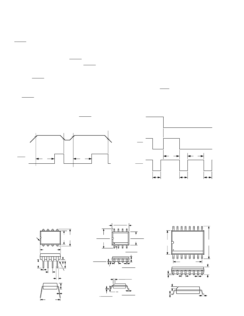
V
2
V
2
V
1
V
1
V
CC
RESET
V
1
= RESET VOLTAGE THRESHOLD
V
2
= RESET VOLTAGE THRESHOLD +
THRESHOLD HYSTERESIS
t
1
= RESET TIME
t
1
t
1
Figure 4. Watchdog Timeout Period vs. Temperature
Watchdog T imer (ADM8699 Only)
T he watchdog timer input (WDI) monitors an I/O line from the
μ
P system. T he
μ
P must toggle this input once every 1.6 sec-
onds to verify correct software execution. Failure to toggle the
line indicates that the
μ
P system is not correctly executing its
program and may be tied up in an endless loop. If this happens,
a reset pulse is generated to initialize the processor.
T he WDI input is a three level input and will recognize a low-
to-high or high-to-low transition on its input. T he watchdog
timer is reset by each WDI transition and then begins its timeout
period. If the WDI pin remains either high or low, reset pulses
will be issued every 1.6 seconds typically. If the watchdog timer
is not needed, the WDI input should be left floating.
T he Watchdog Output (
WDO
) (SOIC package Only) provides
watchdog status information. It is driven low if WDI is not
toggled within the watchdog timeout period. It goes high at the
next WDI transition. It is also set high when V
CC
falls below the
reset threshold.
t
1 = RESET TIME
t
2 = WATCHDOG TIME OUT PERIOD
t
1
t
1
WDI
RESET
t
1
WDO
t
2
t
2
Figure 5. Watchdog Timeout Period and Reset Active Time
OUT LINE DIME NSIONS
Dimensions shown in inches and (mm).
8-Pin Plastic DIP (N-8)
8-Pin SOIC (R-8)
16-Lead SOIC (R-16)
PIN 1
SEATING
PLANE
0.430 (10.92)
MAX
1
4
5
8
0.018 (0.46)
0.033 (0.84)
0.1 (2.54)
BSC
0.125
(3.18)
MIN
0.035
(0.89)
0.18 (4.57)
0.25
(6.35)
0.31
(7.87)
0.011
(0.28)
0.18
(4.57)
MAX
0.3 (7.62)
8
5
4
1
0.1968 (5.00)
0.1890 (4.80)
0.1574 (4.00)
0.1497 (3.80)
0.2440 (6.20)
0.2284 (5.80)
PIN 1
SEATING
PLANE
0.0098 (0.25)
0.0040 (0.10)
0.0192 (0.49)
0.0138 (0.35)
0.102 (2.59)
0.094 (2.39)
0.0500
(1.27)
BSC
0.0098 (0.25)
0.0075 (0.19)
0.0500 (1.27)
0.0160 (0.41)
8
°
0
°
0.0196 (0.50)
°
0.019 (0.49)
0.05 (1.27)
REF
0.104
(2.65)
0.012
(0.3)
0.413 (10.50)
0.419
(10.65)
0.299
(7.60)
1
8
9
16
0.042
(1.07)
0.013
(0.32)
0.030
(0.75)
相关PDF资料 |
PDF描述 |
|---|---|
| ADM8698ARW | Dual Input Li-Ion Charger with Dynamic Power-Path Management, Output regulated to 6V, Vbat 4.2V 20-QFN -40 to 85 |
| ADM8699AN | Microprocessor Supervisory Circuits |
| ADM8699ARN | Dual Input Li-Ion Charger with Dynamic Power-Path Management, Output Regulated to 6V Battery 20-QFN -40 to 125 |
| ADM8699ARW | Dual Input Li-Ion Charger with Dynamic Power-Path Management, Output Regulated to 6V Battery 20-QFN -40 to 125 |
| ADM8698 | Microprocessor Supervisory Circuits(微处理器监控电路) |
相关代理商/技术参数 |
参数描述 |
|---|---|
| ADM8698ARN-REEL | 制造商:Analog Devices 功能描述:Processor Supervisor 4.65V 3V to 5.5V 8-Pin SOIC N T/R 制造商:Analog Devices 功能描述:IMPROVED ADM698 - Tape and Reel 制造商:Rochester Electronics LLC 功能描述:IMPROVED ADM698 - Tape and Reel |
| ADM8698ARNZ | 制造商:Analog Devices 功能描述:Processor Supervisor 4.65V 3V to 5.5V 8-Pin SOIC N 制造商:Analog Devices 功能描述:Microprocessor Supervisor |
| ADM8698ARW | 制造商:Analog Devices 功能描述:PROCESSOR SUPERVISOR 4.65V 100UA 16SOIC W - Rail/Tube |
| ADM8698ARW-REEL | 制造商:Analog Devices 功能描述:Processor Supervisor 4.65V 3V to 5.5V 16-Pin SOIC W T/R 制造商:Analog Devices 功能描述:PROCESSOR SUPERVISOR 4.65V 100UA 16SOIC W - Tape and Reel |
| ADM8699 | 制造商:AD 制造商全称:Analog Devices 功能描述:Microprocessor Supervisory Circuits |
发布紧急采购,3分钟左右您将得到回复。