- 您现在的位置:买卖IC网 > PDF目录375262 > ADP3802AR (ANALOG DEVICES INC) Secondary Over-Voltage Protection for 2-4 cell in series Li-Ion/Poly (4.50V) 8-SM8 -40 to 110 PDF资料下载
参数资料
| 型号: | ADP3802AR |
| 厂商: | ANALOG DEVICES INC |
| 元件分类: | 电源管理 |
| 英文描述: | Secondary Over-Voltage Protection for 2-4 cell in series Li-Ion/Poly (4.50V) 8-SM8 -40 to 110 |
| 中文描述: | 2-CHANNEL POWER SUPPLY SUPPORT CKT, PDSO16 |
| 封装: | SOIC-16 |
| 文件页数: | 16/20页 |
| 文件大小: | 256K |
| 代理商: | ADP3802AR |
ADP3801/ADP3802
–16–
REV. 0
NiCad/NiMH Charging
When paired with a low cost, 8-bit microcontroller, the
ADP3801/ADP3802 charges NiCad and NiMH batteries. The
ADP3801/ADP3802 is used to provide a programmable charge
current limit with a fail-safe voltage limit, and the microcontroller
monitors the battery and determines the charge termination.
Common methods for termination are “negative delta V” and
“delta T.” Both methods require that the present value of either
the voltage or temperature be compared to a previous value.
Such functionality is performed by an
μ
C with an on-board
ADC.
The
μ
C and the ADP3801/ADP3802 are configured as shown
in Figure 30 for the universal charger. The voltage setting on the
ADP3801/ADP3802 should not interfere with normal charging,
but still provide a fail safe voltage if the battery is removed. For
example, if a 6-cell NiCad battery is being charged, the output
voltage of the ADP3801/ADP3802 should be programmed to
12.6 V. The 6-cell battery has a peak voltage of approximately
1.7 V–1.8 V per cell, giving a total voltage of 9.6 V–10.8 V.
Thus, the 12.6 V setting provides enough headroom for normal
charging.
Universal Battery Charger
The combination of a
μ
C and the ADP3801/ADP3802 can be
extended to a low cost universal charger for Li-Ion and NiCad/
NiMH as shown in Figure 30. The
μ
C with on-board A/D con-
verter monitors the battery’s voltage and temperature to deter-
mine the end-of-charge for either NiCad or NiMH batteries.
The ADP3801/ADP3802 also monitors the battery voltage to
determine the end-of-charge for Li-Ion. The
EOC
output is
connected to a digital input on the
μ
C for signaling. The
μ
C can
shutdown the charger circuitry when it is not required. The
μ
C
shown operates from 3.3 V, so it can be powered directly from
the LDO of the ADP3801/ADP3802. The LDO voltage also
serves as a 1% reference for the
μ
C’s ADC.
VCC
ISET
BATA
GND
PROG
EOC
ADP3801/
ADP3802
CHARGER CIRCUIT
VL
SD
PA1
PA0
AN1
AN0
PA2
PA3
VDD
C1
R1
C2
R4
R5
R2
R3
C3
T
VIN
MICRO-
CONTROLLER
T = BATTERY
THERMISTOR
Figure 30. Universal Battery Charger Block Diagram
Both the charge current and the final battery voltage can be
dynamically set by using a PWM output from the
μ
C. The PWM
inputs to ISET and PROG are filtered by an RC combination to
generate a dc voltage on the pins. This functionality allows
multiple battery types and chemistries to be accommodated in a
single charger circuit.
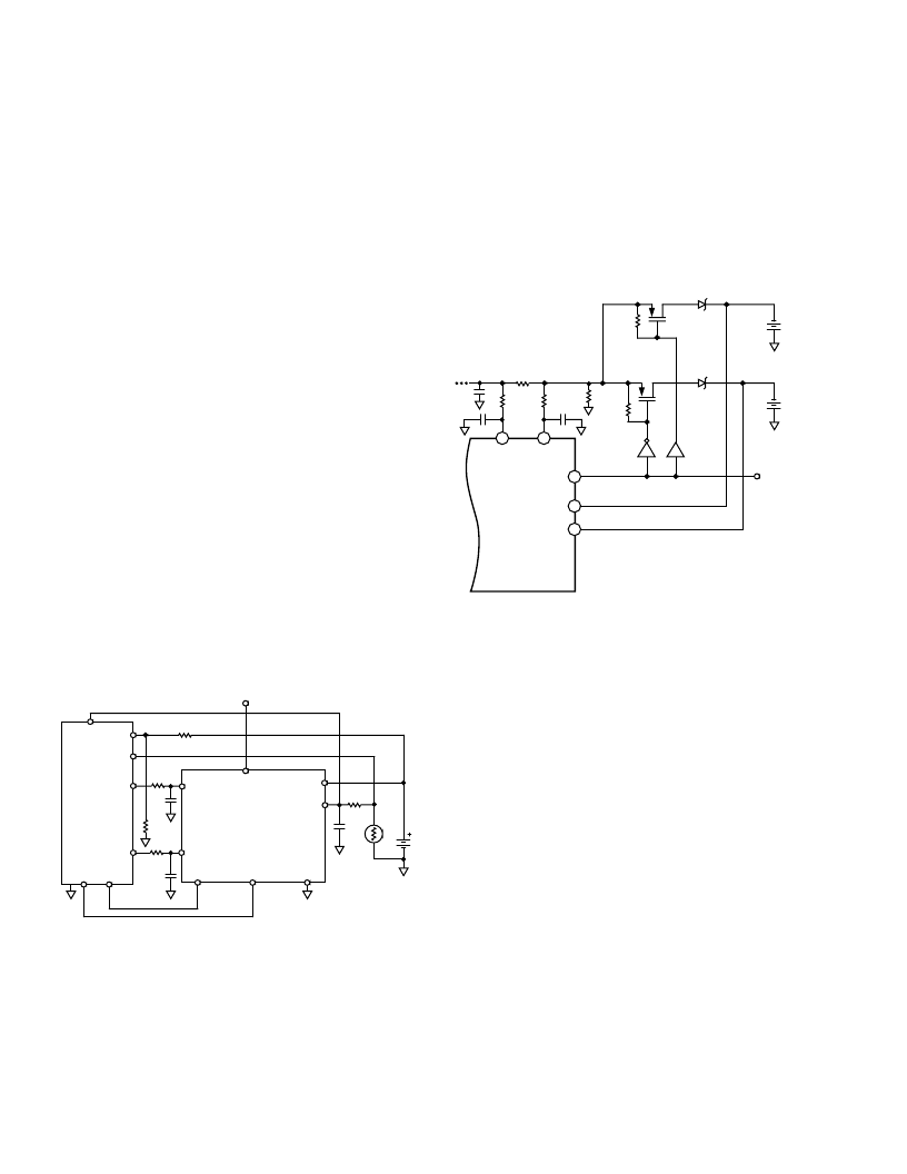
Dual Li-Ion Battery Charger
Some applications such as certain desktop chargers for cellular
phones or laptops with two batteries require that two separate
battery stacks be charged independently. The ADP3801/ADP3802
is designed to handle these applications with two battery sense
inputs and a multiplexer to select between the two. The applica-
tion circuit is essentially the same as Figure 24 except that exter-
nal FETs must be added to direct the charge current to the
proper battery stack. Figure 31 shows the additional circuitry
needed.
Si4463
4.3k
V
BATA
BATB
A/B
CS–
CS+
4.3k
V
ADP3801/
ADP3802
R
CS
40m
V
100k
V
100k
V
Si4463
MBRD835
BATA
BATB
A
/B
SELECTOR
*
*
*
OPEN-COLLECTOR OUTPUTS
MBRD835
R
B
C
O
Figure 31. Dual Li
-
Ion Battery Charger
To provide alternate or sequential charging, the two separate
batteries are alternately connected to the output of the charger
by two Si4463 PFETs. The control of these FETs is accom-
plished by open-collector logic outputs and 100 k
pull-up
resistors. The programming of the A/B terminal should come
from a 0 V to 3.3 V logic output. Most likely a dedicated logic
circuit or a microcontroller would control the system. The
BATB sense input is enabled by connecting a >2 V potential to
the A/B input (or <0.8 V to select BATA). The A and B battery
voltages are directly sensed by the BATA and BATB inputs.
Two Schottky diodes are also included to prevent one battery
stack from shorting to the other through the body diodes of the
FETs. When the charger has finished charging one battery (sig-
naled by the
EOC
output), the MUX and external FETs can be
switched to charge the second battery. When switching from
one battery to the next the following procedure is recommended
to minimize transient currents:
1. Turn off the ADP3801/ADP3802 PWM by bringing the
SD
pin low.
2. Turn off the FET to the battery being charged.
3. Wait approximately 60 seconds for C
O
to discharge through
R
B
.
4. Turn on the FET to the second battery.
5. Change the A/B SELECT MUX to the second battery.
6. Turn on the ADP3801/ADP3802 by bringing the
SD
pin
high.
相关PDF资料 |
PDF描述 |
|---|---|
| ADP3810 | Secondary Side, Off-Line Battery Charger Controllers(电池充电控制器) |
| ADP3811 | Secondary Side, Off-Line Battery Charger Controllers(电池充电控制器) |
| ADP667 | +5 V Fixed, Adjustable Low-Dropout Linear Voltage Regulator |
| ADP667AN | +5 V Fixed, Adjustable Low-Dropout Linear Voltage Regulator |
| ADP667AR | +5 V Fixed, Adjustable Low-Dropout Linear Voltage Regulator |
相关代理商/技术参数 |
参数描述 |
|---|---|
| ADP3804 | 制造商:AD 制造商全称:Analog Devices 功能描述:High Frequency Switch Mode Li-Ion Battery Charger |
| ADP3804JRU | 制造商:AD 制造商全称:Analog Devices 功能描述:High Frequency Switch Mode Li-Ion Battery Charger |
| ADP3804JRU-125 | 制造商:AD 制造商全称:Analog Devices 功能描述:High Frequency Switch Mode Li-Ion Battery Charger |
| ADP3804JRU-126 | 制造商:AD 制造商全称:Analog Devices 功能描述:High Frequency Switch Mode Li-Ion Battery Charger |
| ADP3806 | 制造商:AD 制造商全称:Analog Devices 功能描述:High-Frequency Switch Mode Li-Ion Battery Charger |
发布紧急采购,3分钟左右您将得到回复。