- 您现在的位置:买卖IC网 > PDF目录375262 > ADS1203 MOTOR CONTROL CURRENT MEASUREMENT PDF资料下载
参数资料
| 型号: | ADS1203 |
| 英文描述: | MOTOR CONTROL CURRENT MEASUREMENT |
| 中文描述: | 电机控制电流测量 |
| 文件页数: | 15/24页 |
| 文件大小: | 276K |
| 代理商: | ADS1203 |
SBAS318 JUNE 2004
www.ti.com
15
DIGITAL OUTPUT
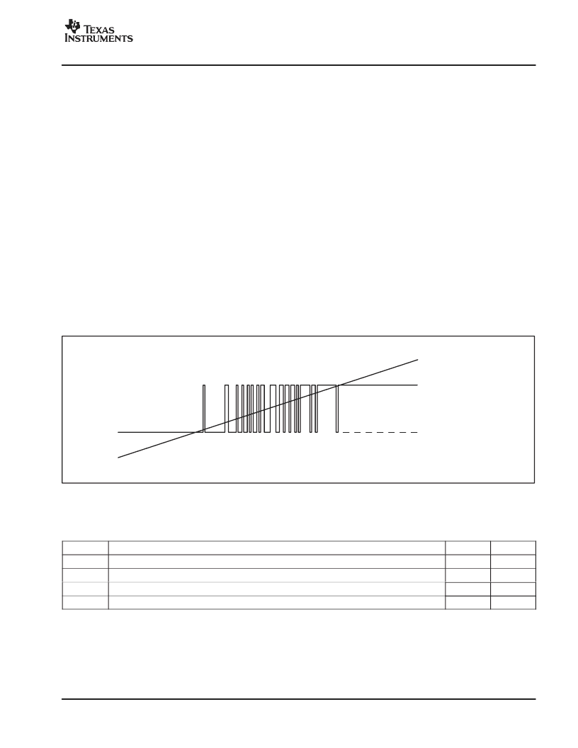
A differential input signal of 0V will ideally produce a
stream of ones and zeros that are high 50% of the time
and low 50% of the time. A differential input of +256mV
will produce a stream of ones and zeros that are high
80% of the time. A differential input of –256mV will
produce a stream of ones and zeros that are high 20%
of the time. The input voltage versus the output
modulator signal is shown in Figure 8.
DIGITAL INTERFACE
INTRODUCTION
The analog signal that is connected to the input of the
delta-sigma modulator is converted using the clock
signal applied to the modulator. The result of the
conversion, or modulation, is the output signal DATA
from the delta-sigma modulator. In most applications
where a direct connection is realized between the
delta-sigma modulator and an ASIC, FPGA, DSP, or
μ
C
(each with an implemented filter), the two standard
signals (MCLK and MDAT) are provided from the
modulator. To reduce the wiring (for example, for
galvanic isolation), a single line is preferred. Therefore,
in mode 2, the data stream is Manchester encoded.
MODES OF OPERATION
The system clock of the ADS1203 is 20MHz by default.
The system clock can be provided either from the
internal 20MHz RC oscillator or from an external clock
source. For this purpose, the MCLK pin is bidirectional
and controlled by the mode setting.
The system clock is divided by 2 for the modulator
clock. Therefore, the default clock frequency of the
modulator is 10MHz. With a possible external clock
range of 1MHz to 32MHz, the modulator operates
between 500kHz and 16MHz.
The four modes of operation for the digital data interface
are shown in Table 1.
Modulator Output
Analog Input
+FS (Analog Input)
FS (Analog Input)
Figure 8. Analog Input vs Modulator Output of the ADS1203
Table 1. Digital Data Interface Modes of Operation
MODE
DEFINITION
M1
M0
0
Internal clock, synchronous data output
Low
Low
1
Internal clock, synchronous data output, half output clock frequency
Low
High
2
Internal clock, Manchester encoded data output
High
Low
3
External clock, synchronous data output
High
High
相关PDF资料 |
PDF描述 |
|---|---|
| ADS1203IPWR | MOTOR CONTROL CURRENT MEASUREMENT |
| ADS1203IPWT | S/P 20 RED REV M |
| ADS1217 | 8-Channel, 24-Bit ANALOG-TO-DIGITAL CONVERTER |
| ADS1217IPFBR | 8-Channel, 24-Bit ANALOG-TO-DIGITAL CONVERTER |
| ADS1217IPFBT | 8-Channel, 24-Bit ANALOG-TO-DIGITAL CONVERTER |
相关代理商/技术参数 |
参数描述 |
|---|---|
| ADS1203IPWR | 功能描述:模数转换器 - ADC Current Shunt D-S Modulator RoHS:否 制造商:Texas Instruments 通道数量:2 结构:Sigma-Delta 转换速率:125 SPs to 8 KSPs 分辨率:24 bit 输入类型:Differential 信噪比:107 dB 接口类型:SPI 工作电源电压:1.7 V to 3.6 V, 2.7 V to 5.25 V 最大工作温度:+ 85 C 安装风格:SMD/SMT 封装 / 箱体:VQFN-32 |
| ADS1203IPWRG4 | 功能描述:模数转换器 - ADC Current Shunt D-S Modulator RoHS:否 制造商:Texas Instruments 通道数量:2 结构:Sigma-Delta 转换速率:125 SPs to 8 KSPs 分辨率:24 bit 输入类型:Differential 信噪比:107 dB 接口类型:SPI 工作电源电压:1.7 V to 3.6 V, 2.7 V to 5.25 V 最大工作温度:+ 85 C 安装风格:SMD/SMT 封装 / 箱体:VQFN-32 |
| ADS1203IPWT | 功能描述:模数转换器 - ADC Current Shunt D-S Modulator RoHS:否 制造商:Texas Instruments 通道数量:2 结构:Sigma-Delta 转换速率:125 SPs to 8 KSPs 分辨率:24 bit 输入类型:Differential 信噪比:107 dB 接口类型:SPI 工作电源电压:1.7 V to 3.6 V, 2.7 V to 5.25 V 最大工作温度:+ 85 C 安装风格:SMD/SMT 封装 / 箱体:VQFN-32 |
| ADS1203IPWTG4 | 功能描述:模数转换器 - ADC Current Shunt D-S Modulator RoHS:否 制造商:Texas Instruments 通道数量:2 结构:Sigma-Delta 转换速率:125 SPs to 8 KSPs 分辨率:24 bit 输入类型:Differential 信噪比:107 dB 接口类型:SPI 工作电源电压:1.7 V to 3.6 V, 2.7 V to 5.25 V 最大工作温度:+ 85 C 安装风格:SMD/SMT 封装 / 箱体:VQFN-32 |
| ADS1203IRGTR | 功能描述:模数转换器 - ADC Current Shunt D-S Modulator RoHS:否 制造商:Texas Instruments 通道数量:2 结构:Sigma-Delta 转换速率:125 SPs to 8 KSPs 分辨率:24 bit 输入类型:Differential 信噪比:107 dB 接口类型:SPI 工作电源电压:1.7 V to 3.6 V, 2.7 V to 5.25 V 最大工作温度:+ 85 C 安装风格:SMD/SMT 封装 / 箱体:VQFN-32 |
发布紧急采购,3分钟左右您将得到回复。