- 您现在的位置:买卖IC网 > PDF目录10381 > ADS62P42IRGCR (Texas Instruments)IC ADC 14BIT SER/PAR 65M 64VQFN PDF资料下载
参数资料
| 型号: | ADS62P42IRGCR |
| 厂商: | Texas Instruments |
| 文件页数: | 44/78页 |
| 文件大小: | 0K |
| 描述: | IC ADC 14BIT SER/PAR 65M 64VQFN |
| 产品培训模块: | Data Converter Basics |
| 标准包装: | 2,000 |
| 位数: | 14 |
| 采样率(每秒): | 65M |
| 数据接口: | 串行,并联 |
| 转换器数目: | 2 |
| 电压电源: | 模拟和数字 |
| 工作温度: | -40°C ~ 85°C |
| 安装类型: | 表面贴装 |
| 封装/外壳: | 64-VFQFN 裸露焊盘 |
| 供应商设备封装: | 64-VQFN 裸露焊盘(9x9) |
| 包装: | 带卷 (TR) |
| 输入数目和类型: | 2 个差分,单极 |
第1页第2页第3页第4页第5页第6页第7页第8页第9页第10页第11页第12页第13页第14页第15页第16页第17页第18页第19页第20页第21页第22页第23页第24页第25页第26页第27页第28页第29页第30页第31页第32页第33页第34页第35页第36页第37页第38页第39页第40页第41页第42页第43页当前第44页第45页第46页第47页第48页第49页第50页第51页第52页第53页第54页第55页第56页第57页第58页第59页第60页第61页第62页第63页第64页第65页第66页第67页第68页第69页第70页第71页第72页第73页第74页第75页第76页第77页第78页
f Frequency MHz
0
1
2
3
4
5
6
7
8
9
0
100
200
300
400
500
600
C
Capacitance
pF
G082
S0163-03
INP
INM
VCM
1:1
ADS62P4x
25 W
0.1 F
m
0.1 F
m
SLAS561C
– JULY 2007 – REVISED FEBRUARY 2012
Figure 85. ADC Analog Input Capacitance (Cin) Across Frequency
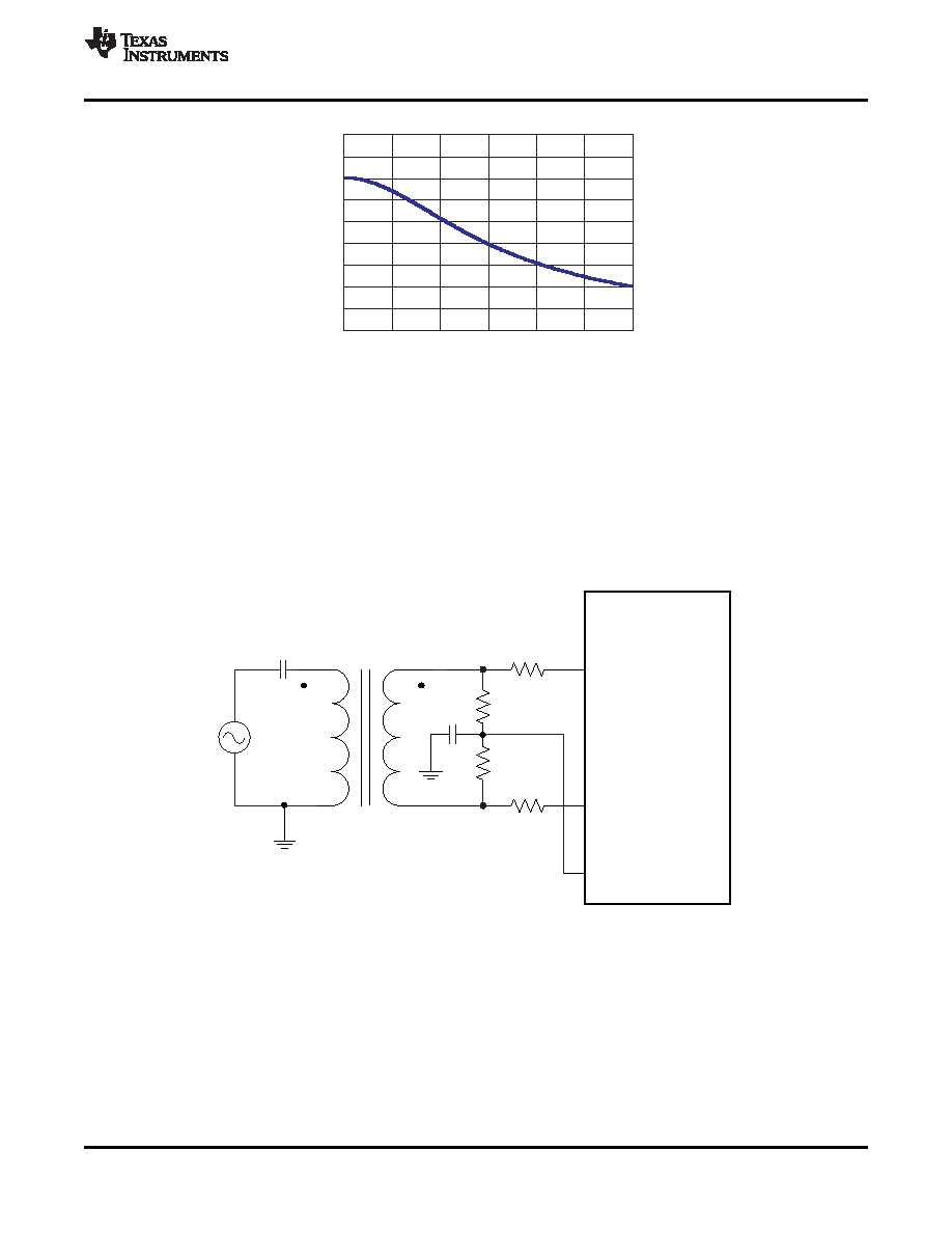
Using RF-Transformer Based Drive Circuits
Figure 86 shows a configuration using a single 1:1 turns ratio transformer (for example, Coilcraft WBC1-1) that
can be used for low input frequencies (about 100 MHz). The single-ended signal is fed to the primary winding of
the RF transformer. The transformer is terminated on the secondary side. Putting the termination on the
secondary side helps to shield the kickbacks caused by the sampling circuit from the RF transformer
’s leakage
inductances. The termination is accomplished by two resistors connected in series, with the center point
connected to the 1.5-V common mode (VCM). The value of the termination resistors (connected to common
mode) has to be low (
<100 ) to provide a low-impedance path for the ADC common-mode switching currents.
Figure 86. Drive Circuit at Low Input Frequencies
At high input frequencies, the mismatch in the transformer parasitic capacitance (between the windings) results
in degraded even-order harmonic performance. Connecting two identical RF transformers back-to-back helps
minimize this mismatch, and good performance is obtained for high frequency input signals. Figure 87 shows an
example using two transformers (Coilcraft WBC1-1). An additional termination resistor pair (enclosed within the
shaded box) may be required between the two transformers to improve the balance between the P and M sides.
The center point of this termination must be connected to ground.
Copyright
2007–2012, Texas Instruments Incorporated
49
Product Folder Link(s): ADS62P45, ADS62P44 ADS62P43, ADS62P42
相关PDF资料 |
PDF描述 |
|---|---|
| VE-BWB-IV-F4 | CONVERTER MOD DC/DC 95V 150W |
| VE-JVP-MY-B1 | CONVERTER MOD DC/DC 13.8V 50W |
| VE-BNY-IU-F4 | CONVERTER MOD DC/DC 3.3V 132W |
| VE-BNX-IV-F3 | CONVERTER MOD DC/DC 5.2V 150W |
| VE-JVL-MY-B1 | CONVERTER MOD DC/DC 28V 50W |
相关代理商/技术参数 |
参数描述 |
|---|---|
| ADS62P42IRGCRG4 | 功能描述:模数转换器 - ADC DUAL 14B 65MSPS Para ADC RoHS:否 制造商:Texas Instruments 通道数量:2 结构:Sigma-Delta 转换速率:125 SPs to 8 KSPs 分辨率:24 bit 输入类型:Differential 信噪比:107 dB 接口类型:SPI 工作电源电压:1.7 V to 3.6 V, 2.7 V to 5.25 V 最大工作温度:+ 85 C 安装风格:SMD/SMT 封装 / 箱体:VQFN-32 |
| ADS62P42IRGCT | 功能描述:模数转换器 - ADC Dual 14B 65MSPS ADC RoHS:否 制造商:Texas Instruments 通道数量:2 结构:Sigma-Delta 转换速率:125 SPs to 8 KSPs 分辨率:24 bit 输入类型:Differential 信噪比:107 dB 接口类型:SPI 工作电源电压:1.7 V to 3.6 V, 2.7 V to 5.25 V 最大工作温度:+ 85 C 安装风格:SMD/SMT 封装 / 箱体:VQFN-32 |
| ADS62P42IRGCTG4 | 功能描述:模数转换器 - ADC DUAL 14B 65MSPS Para ADC RoHS:否 制造商:Texas Instruments 通道数量:2 结构:Sigma-Delta 转换速率:125 SPs to 8 KSPs 分辨率:24 bit 输入类型:Differential 信噪比:107 dB 接口类型:SPI 工作电源电压:1.7 V to 3.6 V, 2.7 V to 5.25 V 最大工作温度:+ 85 C 安装风格:SMD/SMT 封装 / 箱体:VQFN-32 |
| ADS62P42RGC | 制造商:TI 制造商全称:Texas Instruments 功能描述:Dual Channel 14-Bit, 125/105/80/65 MSPS ADC with Parallel CMOS/DDR LVDS outputs |
| ADS62P43 | 制造商:TI 制造商全称:Texas Instruments 功能描述:DUAL CHANNEL, 14-BITS, 125/105/80/65 MSPS ADC WITH DDR LVDS/CMOS OUTPUTS |
发布紧急采购,3分钟左右您将得到回复。