- 您现在的位置:买卖IC网 > PDF目录67358 > ADT7473ARQZ-1REEL7 (ANALOG DEVICES INC) DIGITAL TEMP SENSOR-SERIAL, 8BIT(s), 2.50Cel, RECTANGULAR, SURFACE MOUNT PDF资料下载
参数资料
| 型号: | ADT7473ARQZ-1REEL7 |
| 厂商: | ANALOG DEVICES INC |
| 元件分类: | 温度/湿度传感器 |
| 英文描述: | DIGITAL TEMP SENSOR-SERIAL, 8BIT(s), 2.50Cel, RECTANGULAR, SURFACE MOUNT |
| 封装: | ROHS COMPLIANT, MO-137AB, QSOP-16 |
| 文件页数: | 14/72页 |
| 文件大小: | 1494K |
| 代理商: | ADT7473ARQZ-1REEL7 |
第1页第2页第3页第4页第5页第6页第7页第8页第9页第10页第11页第12页第13页当前第14页第15页第16页第17页第18页第19页第20页第21页第22页第23页第24页第25页第26页第27页第28页第29页第30页第31页第32页第33页第34页第35页第36页第37页第38页第39页第40页第41页第42页第43页第44页第45页第46页第47页第48页第49页第50页第51页第52页第53页第54页第55页第56页第57页第58页第59页第60页第61页第62页第63页第64页第65页第66页第67页第68页第69页第70页第71页第72页
ADT7473/ADT7473-1
Rev. C | Page 21 of 72
INTERRUPT STATUS REGISTERS
The results of limit comparisons are stored in Interrupt Status
Register 1 and Interrupt Status Register 2. The status register bit
for each channel reflects the status of the last measurement and
limit comparison on that channel. If a measurement is within
limits, the corresponding status register bit is cleared to 0. If the
measurement is out of limits, the corresponding status register
bit is set to 1.
The state of the various measurement channels can be polled by
reading the status registers over the serial bus. In Bit 7 (OOL) of
Interrupt Status Register 1 (Reg. 0x41), a 1 means an out-of-limit
event has been flagged in Interrupt Status Register 2. This means
the user needs only to read Interrupt Status Register 2 when this bit
is set. Alternatively, Pin 5 or Pin 9 on the ADT7473 can be config-
ured as an SMBALERT output, while only Pin 9 can be configured
to be an SMBALERT on the ADT7473-1. This automatically
notifies the system supervisor of an out-of-limit condition.
Reading the status registers clears the appropriate status bit as
long as the error condition that caused the interrupt has cleared.
Status register bits (except OVT) are sticky. Whenever a status bit
is set, indicating an out-of-limit condition, it remains set even if the
event that caused it has gone away (until read). The only way to
clear the status bit is to read the status register after the event has
gone away. Interrupt mask registers (Register 0x74 and Register
0x75) allow individual interrupt sources to be masked from causing
an SMBALERT. However, if one of these masked interrupt sources
goes out of limit, its associated status bit is set in the interrupt status
registers. OVT clears automatically.
Interrupt Status Register 1 (0x41)
Bit 7 (OOL) = 1, denotes a bit in Interrupt Status Register 2 is
set and Interrupt Status Register 2 should be read.
Bit 6 (R2T) = 1, Remote 2 temperature high or low limit has
been exceeded.
Bit 5 (LT) = 1, local temperature high or low limit has been
exceeded.
Bit 4 (R1T) = 1, Remote 1 temperature high or low limit has
been exceeded.
Bit 2 (VCC) = 1, VCC high or low limit has been exceeded.
Bit 1 (VCCP) = 1, VCCP high or low limit has been exceeded.
Interrupt Status Register 2 (0x42)
Bit 7 (D2) = 1, indicates an open or short on D2+/D2– inputs.
Bit 6 (D1) = 1, indicates an open or short on D1+/D1– inputs.
Bit 5 (F4P) = 1, indicates Fan 4 has dropped below the
minimum speed. Alternatively, it indicates the THERM limit
has been exceeded, if the THERM function is used.
Bit 4 (FAN3) = 1, indicates Fan 3 has dropped below the
minimum speed.
Bit 3 (FAN2) = 1, indicates Fan 2 has dropped below the
minimum speed.
Bit 2 (FAN1) = 1, indicates that Fan 1 dropped below the
minimum speed.
Bit 1 (OVT) = 1, indicates that a THERM overtemperature limit
has been exceeded.
Bit 0 (THERM Limit Latch) = 1, indicates a Remote Channel 2
latch.
SMBALERT Interrupt Behavior
The ADT747/ADT7473-1 can be polled for status, or an
SMBALERT interrupt can be generated for out-of-limit
conditions. It is important to note how the SMBALERT output
and status bits behave when writing interrupt handler software.
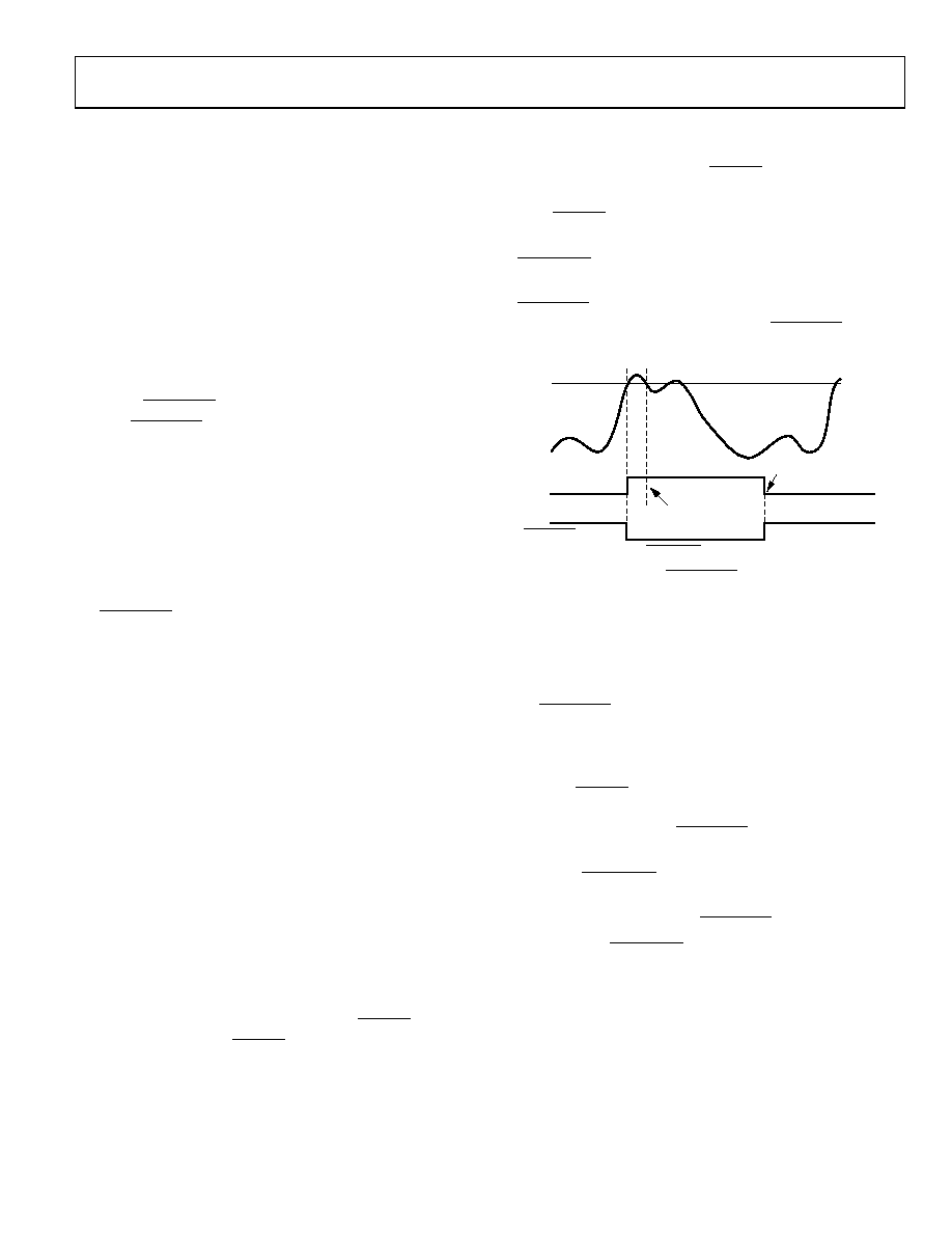
STICKY
STATUS BIT
HIGH LIMIT
TEMPERATURE
CLEARED ON READ
(TEMP BELOW LIMIT)
TEMP BACK IN LIMIT
(STATUS BIT STAYS SET)
SMBALERT
04
686
-028
Figure 31. SMBALERT and Status Bit Behavior
Figure 31 shows how the SMBALERT output and sticky status
bits behave. Once a limit is exceeded, the corresponding status
bit is set to 1. The interrupt status bit remains set until the error
condition subsides and the interrupt status register is read. The
status bits are referred to as sticky because they remain set until
read by software. This ensures that an out-of-limit event cannot
be missed if software is polling the device periodically. Note that
the SMBALERT output remains low for the entire duration that
a reading is out of limit and until the interrupt status register
has been read. This has implications on how software handles
the interrupt.
Note that THERM overtemperature events are not sticky,
resetting immediately after the overtemperature condition
ceases. This also applies to SMBALERT if associated with an
OVT event.
Handling SMBALERT Interrupts
To prevent the system from being tied up servicing interrupts, it
is recommended to handle the SMBALERT interrupt as follows:
1.
Detect the SMBALERT assertion.
2.
Enter the interrupt handler.
3.
Read the status registers to identify the interrupt source.
4.
Mask the interrupt source by setting the appropriate mask
bit in the interrupt mask registers (Register 0x74 and
Register 0x75).
5.
Take the appropriate action for a given interrupt source.
6.
Exit the interrupt handler.
相关PDF资料 |
PDF描述 |
|---|---|
| ADT7473ARQZ-1REEL | DIGITAL TEMP SENSOR-SERIAL, 8BIT(s), 2.50Cel, RECTANGULAR, SURFACE MOUNT |
| ADT7476ARQZ-REEL7 | DIGITAL TEMP SENSOR-SERIAL, 10BIT(s), 2.50Cel, RECTANGULAR, SURFACE MOUNT |
| ADT7482ARMZ-RL | DIGITAL TEMP SENSOR-SERIAL, 11BIT(s), 2.5Cel, SQUARE, SURFACE MOUNT |
| ADT7482ARMZ-U2 | DIGITAL TEMP SENSOR-SERIAL, 11BIT(s), 2.5Cel, SQUARE, SURFACE MOUNT |
| ADT7485ARMZ-REEL | DIGITAL TEMP SENSOR-SERIAL, 16BIT(s), 1Cel, SQUARE, SURFACE MOUNT |
相关代理商/技术参数 |
参数描述 |
|---|---|
| ADT7473ARQZ-1RL | 功能描述:板上安装温度传感器 FAN CNTRLR/INT MON RoHS:否 制造商:Omron Electronics 输出类型:Digital 配置: 准确性:+/- 1.5 C, +/- 3 C 温度阈值: 数字输出 - 总线接口:2-Wire, I2C, SMBus 电源电压-最大:5.5 V 电源电压-最小:4.5 V 最大工作温度:+ 50 C 最小工作温度:0 C 关闭: 安装风格: 封装 / 箱体: 设备功能:Temperature and Humidity Sensor |
| ADT7473ARQZ-REEL | 功能描述:板上安装温度传感器 FAN CNTRLR/INT MON RoHS:否 制造商:Omron Electronics 输出类型:Digital 配置: 准确性:+/- 1.5 C, +/- 3 C 温度阈值: 数字输出 - 总线接口:2-Wire, I2C, SMBus 电源电压-最大:5.5 V 电源电压-最小:4.5 V 最大工作温度:+ 50 C 最小工作温度:0 C 关闭: 安装风格: 封装 / 箱体: 设备功能:Temperature and Humidity Sensor |
| ADT7473ARQZ-REEL7 | 功能描述:IC REMOTE THERMAL CTRLR 16QSOP RoHS:是 类别:集成电路 (IC) >> PMIC - 热管理 系列:dBCool® 标准包装:1 系列:- 功能:温度监控系统(传感器) 传感器类型:内部和外部 感应温度:-40°C ~ 125°C,外部传感器 精确度:±2.5°C 本地(最大值),±5°C 远程(最大值) 拓扑:ADC,比较器,寄存器库 输出类型:2 线 SMBus? 输出警报:无 输出风扇:无 电源电压:2.7 V ~ 5.5 V 工作温度:-40°C ~ 125°C 安装类型:表面贴装 封装/外壳:SOT-23-8 供应商设备封装:SOT-23-8 包装:Digi-Reel® 其它名称:296-22675-6 |
| ADT7473ARQZ-RL7 | 功能描述:板上安装温度传感器 FAN CNTRLR/INT MON RoHS:否 制造商:Omron Electronics 输出类型:Digital 配置: 准确性:+/- 1.5 C, +/- 3 C 温度阈值: 数字输出 - 总线接口:2-Wire, I2C, SMBus 电源电压-最大:5.5 V 电源电压-最小:4.5 V 最大工作温度:+ 50 C 最小工作温度:0 C 关闭: 安装风格: 封装 / 箱体: 设备功能:Temperature and Humidity Sensor |
| ADT7473EBZEVB | 功能描述:EVALUATION BOARD ADT7473 制造商:on semiconductor 系列:* 零件状态:在售 标准包装:1 |
发布紧急采购,3分钟左右您将得到回复。