- 您现在的位置:买卖IC网 > PDF目录22020 > ADT7476ARQZ (ON Semiconductor)IC REMOTE THERMAL CTLR 24QSOP PDF资料下载
参数资料
| 型号: | ADT7476ARQZ |
| 厂商: | ON Semiconductor |
| 文件页数: | 30/65页 |
| 文件大小: | 0K |
| 描述: | IC REMOTE THERMAL CTLR 24QSOP |
| 产品变化通告: | MFG CHG Notification ADI to ON Semi QSOP 24ld Pkg (MSL) Change 17/Jun/2010 Product Discontinuation 30/Sept/2011 |
| 标准包装: | 56 |
| 系列: | dBCool® |
| 功能: | 风扇控制,温度监控器 |
| 传感器类型: | 内部和外部 |
| 感应温度: | -40°C ~ 125°C |
| 精确度: | ±2.5% |
| 拓扑: | ADC,比较器,风扇速度计数器,多路复用器,寄存器库 |
| 输出类型: | SMBus? |
| 输出警报: | 无 |
| 输出风扇: | 是 |
| 电源电压: | 3 V ~ 3.6 V |
| 工作温度: | -40°C ~ 125°C |
| 安装类型: | 表面贴装 |
| 封装/外壳: | 24-SSOP(0.154",3.90mm 宽) |
| 供应商设备封装: | 24-QSOP |
| 包装: | 管件 |
| 其它名称: | ADT7476ARQZ-ND ADT7476ARQZOS |
第1页第2页第3页第4页第5页第6页第7页第8页第9页第10页第11页第12页第13页第14页第15页第16页第17页第18页第19页第20页第21页第22页第23页第24页第25页第26页第27页第28页第29页当前第30页第31页第32页第33页第34页第35页第36页第37页第38页第39页第40页第41页第42页第43页第44页第45页第46页第47页第48页第49页第50页第51页第52页第53页第54页第55页第56页第57页第58页第59页第60页第61页第62页第63页第64页第65页
�� �
�
�ADT7476�
�dc� bits� are� automatically� asserted� internally� and� do� not� need�
�to� be� changed.�
�Fan� Speed� Control�
�The� ADT7476� controls� fan� speed� using� automatic� and�
�manual� modes:�
�?� In� automatic� fan� speed� control� mode,� fan� speed� is�
�automatically� varied� with� temperature� and� without� CPU�
�intervention� once� initial� parameters� are� set� up.� The�
�advantage� is� that� if� the� system� hangs,� the� user� is�
�guaranteed� that� the� system� is� protected� from�
�overheating.�
�?� In� manual� fan� speed� control� mode,� the� ADT7476�
�allows� the� duty� cycle� of� any� PWM� output� to� be�
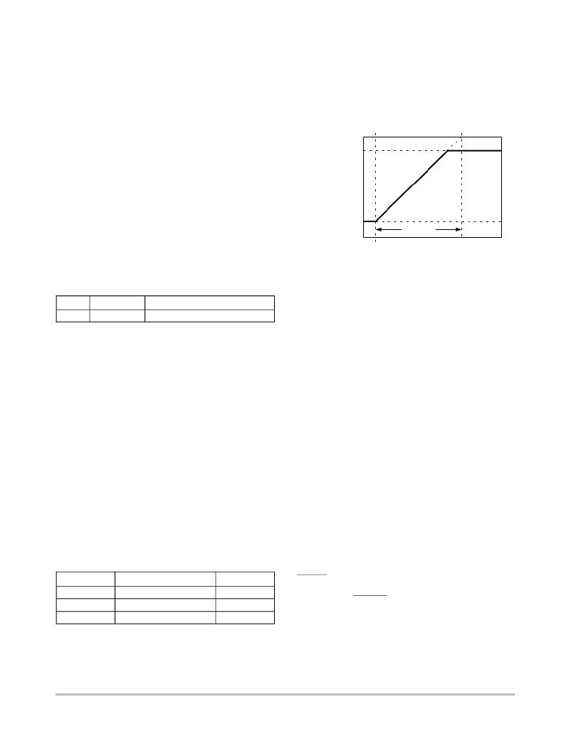
�Programming� T� RANGE�
�T� RANGE� defines� the� distance� between� T� MIN� and� 100%�
�PWM.� For� the� ADT7467,� ADT7468� and� ADT7473,� T� RANGE�
�is� effectively� a� slope.� For� the� ADT7475� andADT7476,�
�T� RANGE� is� no� longer� a� slope,� but� defines� the� temperature�
�region� where� the� PWM� output� linearly� ramps� from� PWM� MIN�
�to� 100%� PWM.�
�PWM� =� 100%�
�PWM� MAX�
�adjusted� manually.� This� can� be� useful� if� the� user� wants�
�to� change� fan� speed� in� software� or� adjust� PWM� duty�
�cycle� output� for� test� purposes.� Bits� [7:5]� of� Register�
�0x5C� to� Register� 0x5E� (PWM� Configuration)� control�
�the� behavior� of� each� PWM� output.�
�PWM� MIN�
�PWM� =� 0%�
�T� RANGE�
�T� MIN�
�Figure� 46.� T� RANGE�
�Table� 42.� PWM� CONFIGURATION�
�(REG.� 0X5C� TO� 0X5E)� BITS�
�Bit� Mnemonic� Description�
�[7:5]� BHVR� 111� =� Manual� Mode�
�Once� under� manual� control,� each� PWM� output� can� be�
�manually� updated� by� writing� to� Register� 0x30� to� Register�
�0x32� (PWM� current� duty� cycle� registers).�
�Programming� the� PWM� Current� Duty� Cycle� Registers�
�The� PWM� current� duty� cycle� registers� are� 8-bit� registers�
�that� allow� the� PWM� duty� cycle� for� each� output� to� be� set�
�anywhere� from� 0%� to� 100%� in� steps� of� 0.39%.� The� value� to�
�be� programmed� into� the� PWM� MIN� register� is� given� by:�
�Value� (decimal)� =� PWM� MIN� /0.39�
�Example� 1:�
�For� a� PWM� duty� cycle� of� 50%,�
�Value� (decimal)� =� 50/0.39� =� 128� (decimal)�
�Value� =� 128� (decimal)� or� 0x80� (hex)�
�Example� 2:�
�For� a� PWM� duty� cycle� of� 33%,�
�Value� (decimal)� =� 33/0.39� =� 85� (decimal)�
�Value� =� 85� (decimal)� or� 0x54� (hex)�
�Table 43. PW� M� CURRENT DUTY CYCL� E� REGISTERS�
�Programming� the� Automatic� Fan� Speed� Control� Loop�
�To� understand� the� automatic� fan� speed� control� loop� more�
�efficiently,� it� is� recommended� to� use� the� ADT7476�
�evaluation� board� and� software� while� reading� this� section.�
�This� section� provides� the� system� designer� with� an�
�understanding� of� the� automatic� fan� control� loop� and�
�provides� step-by-step� guidance� on� effectively� evaluating�
�and� selecting� critical� system� parameters.� To� optimize� the�
�system� characteristics,� the� designer� needs� to� give� some�
�thought� to� system� configuration,� including� the� number� of�
�fans,� where� they� are� located,� and� what� temperatures� are�
�being� measured� in� the� particular� system.�
�The� mechanical� or� thermal� engineer� who� is� tasked� with�
�the� system� thermal� characterization� should� also� be� involved�
�at� the� beginning� of� the� system� development� process.�
�Manual� Fan� Control� Overview�
�In� unusual� circumstances,� it� can� be� necessary� to� manually�
�control� the� speed� of� the� fans.� Because� the� ADT7476� has� an�
�SMBus� interface,� a� system� can� read� back� all� necessary�
�voltage,� fan� speed,� and� temperature� information,� and� use�
�this� information� to� control� the� speed� of� the� fans� by� writing�
�to� the� PWM� current� duty� cycle� register� (0x30,� 0x31,� and�
�0x32)� of� the� appropriate� fan.� Bits� [7:5]� of� the� PWMx�
�configuration� registers� (0x5C,� 0x5D,� 0x5E)� are� used� to� set�
�fans� up� for� manual� control.�
�Register�
�0x30�
�0x31�
�0x32�
�Description�
�PWM1� Current� Duty� Cycle�
�PWM2� Current� Duty� Cycle�
�PWM3� Current� Duty� Cycle�
�Default�
�0xFF� (100%)�
�0xFF� (100%)�
�0xFF� (100%)�
�THERM� Operation� in� Manual� Mode�
�In� manual� mode,� if� the� temperature� increases� above� the�
�programmed� THERM� temperature� limit,� the� fans�
�automatically� speed� up� to� maximum� PWM� or� 100%� PWM,�
�whichever� way� the� appropriate� fan� channel� is� configured.�
�By� reading� the� PWMx� current� duty� cycle� registers,� the�
�user� can� keep� track� of� the� current� duty� cycle� on� each� PWM�
�output,� even� when� the� fans� are� running� in� automatic� fan�
�speed� control� mode� or� acoustic� enhancement� mode.�
�Automatic� Fan� Control� Overview�
�The� ADT7476� can� automatically� control� the� speed� of� fans�
�based� on� the� measured� temperature.� This� is� done�
�http://onsemi.com�
�30�
�相关PDF资料 |
PDF描述 |
|---|---|
| TPSD107K010S0100 | CAP TANT 100UF 10V 10% 2917 |
| ADT7481ARMZ | IC SENSOR TEMP 2CH ALARM 10MSOP |
| AIML-0603-R39K-T | INDUCTOR MULTILAYER 390NH 0603 |
| 4-1879023-7 | INDUCTOR 8.2UH 5% 1008 |
| TAJB474K035RNJ | CAP TANT 0.47UF 35V 10% 1210 |
相关代理商/技术参数 |
参数描述 |
|---|---|
| ADT7476ARQZ-R7 | 功能描述:马达/运动/点火控制器和驱动器 MLTICH TDM FAN CTRLR RoHS:否 制造商:STMicroelectronics 产品:Stepper Motor Controllers / Drivers 类型:2 Phase Stepper Motor Driver 工作电源电压:8 V to 45 V 电源电流:0.5 mA 工作温度:- 25 C to + 125 C 安装风格:SMD/SMT 封装 / 箱体:HTSSOP-28 封装:Tube |
| ADT7476ARQZ-REEL | 功能描述:马达/运动/点火控制器和驱动器 MLTICH TDM FAN CTRLR RoHS:否 制造商:STMicroelectronics 产品:Stepper Motor Controllers / Drivers 类型:2 Phase Stepper Motor Driver 工作电源电压:8 V to 45 V 电源电流:0.5 mA 工作温度:- 25 C to + 125 C 安装风格:SMD/SMT 封装 / 箱体:HTSSOP-28 封装:Tube |
| ADT7476ARQZ-REEL7 | 功能描述:IC REMOTE THERMAL CTRLR 24QSOP RoHS:是 类别:集成电路 (IC) >> PMIC - 热管理 系列:dBCool® 标准包装:1 系列:- 功能:温度监控系统(传感器) 传感器类型:内部和外部 感应温度:-40°C ~ 125°C,外部传感器 精确度:±2.5°C 本地(最大值),±5°C 远程(最大值) 拓扑:ADC,比较器,寄存器库 输出类型:2 线 SMBus? 输出警报:无 输出风扇:无 电源电压:2.7 V ~ 5.5 V 工作温度:-40°C ~ 125°C 安装类型:表面贴装 封装/外壳:SOT-23-8 供应商设备封装:SOT-23-8 包装:Digi-Reel® 其它名称:296-22675-6 |
| ADT7476EBZEVB | 功能描述:BOARD EVALUATION FOR ADT7476 RoHS:是 类别:编程器,开发系统 >> 过时/停产零件编号 系列:dBCool® 标准包装:1 系列:- 传感器类型:CMOS 成像,彩色(RGB) 传感范围:WVGA 接口:I²C 灵敏度:60 fps 电源电压:5.7 V ~ 6.3 V 嵌入式:否 已供物品:成像器板 已用 IC / 零件:KAC-00401 相关产品:4H2099-ND - SENSOR IMAGE WVGA COLOR 48-PQFP4H2094-ND - SENSOR IMAGE WVGA MONO 48-PQFP |
| ADT7481 | 制造商:AD 制造商全称:Analog Devices 功能描述:Dual Channel Temperature Sensor and Over Temperature Alarm |
发布紧急采购,3分钟左右您将得到回复。