- 您现在的位置:买卖IC网 > Datasheet目录308 > ADUM7241CRZ-RL7 (Analog Devices Inc)ISOLATOR DGTL 1KVRMS 2CH 8SOIC Datasheet资料下载
参数资料
| 型号: | ADUM7241CRZ-RL7 |
| 厂商: | Analog Devices Inc |
| 文件页数: | 13/16页 |
| 文件大小: | 0K |
| 描述: | ISOLATOR DGTL 1KVRMS 2CH 8SOIC |
| 标准包装: | 1,000 |
| 系列: | * |
�� �
�
�Data� Sheet�
�1000�
�100�
�10�
�1�
�0.1�
�0.01�
�ADuM7240/ADuM7241�
�Note� that� with� extreme� combinations� of� strong� magnetic� field�
�and� high� frequency� current,� loops� formed� by� printed� circuit�
�board� traces� can� induce� error� voltages� large� enough� to� trigger�
�the� thresholds� of� receiver� circuitry.� Care� should� be� taken� in� the�
�layout� of� such� traces� to� avoid� this� possibility.�
�POWER� CONSUMPTION�
�The� supply� current� at� a� given� channel� of� the� ADuM7240� /�
�ADuM7241� isolator� is� a� function� of� the� supply� voltage,� the�
�data� rate� of� the� channel,� and� the� output� load� of� the� channel.�
�For� each� input� channel,� the� supply� current� is� given� by�
�0.001�
�1k�
�10k�
�100k�
�1M�
�10M�
�100M�
�I� DDI� =� I� DDI� (� Q� )�
�f� ≤� 0.5� f� r�
�MAGNETIC� FIELD� FREQUENCY� (Hz)�
�I� DDI� =� I� DDI(D)� � (2� f� ?� f� r� )� +� I� DDI� (� Q� )�
�f� >� 0.5� f� r�
�I� DDO� =� (� I� DDO(D� )� +� (0.5� � 10� )� � C� L� � V� DDO� )� � (2� f� ?� f� r� )� +� I� DDO� (� Q� )�
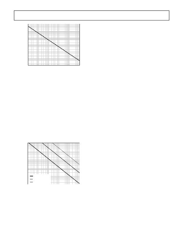
�Figure� 14.� Maximum� Allowable� External� Magnetic� Flux� Density�
�For� example,� at� a� magnetic� field� frequency� of� 1� MHz,� the�
�maximum� allowable� magnetic� field� of� 0.5� kgauss� induces� a�
�voltage� of� 0.25� V� at� the� receiving� coil.� This� voltage� is� about� 50%�
�of� the� sensing� threshold� and� does� not� cause� a� faulty� output�
�transition.� Similarly,� if� such� an� event� occurs� during� a� transmit-�
�ted� pulse� (and� is� of� the� worst-case� polarity),� it� reduces� the�
�received� pulse� from� >1.0� V� to� 0.75� V,� still� well� above� the� 0.5� V�
�sensing� threshold� of� the� decoder.�
�The� preceding� magnetic� flux� density� values� correspond� to�
�specific� current� magnitudes� at� given� distances� from� the�
�ADuM7240� /� ADuM7241� transformers.� Figure� 15� shows� these�
�allowable� current� magnitudes� as� a� function� of� frequency� for�
�selected� distances.� As� shown� in� Figure� 15,� the� ADuM7240� /�
�ADuM7241� is� extremely� immune� and� can� be� affected� only� by�
�extremely� large� currents� operated� at� high� frequency� very� close�
�to� the� component.� For� the� 1� MHz� example,� a� 1.2� kA� current�
�placed� 5� mm� away� from� the� ADuM7240� /� ADuM7241� is�
�required� to� affect� the� operation� of� the� component.�
�1000�
�100�
�10�
�1�
�For� each� output� channel,� the� supply� current� is� given� by�
�I� DDO� =� I� DDO� (� Q� )� f� ≤� 0.5� f� r�
�?3�
�f� >� 0.5� f� r�
�where:�
�I� DDI(D)� ,� I� DDO(D)� are� the� input� and� output� dynamic� supply� currents�
�per� channel� (mA/Mbps).�
�C� L� is� the� output� load� capacitance� (pF).�
�V� DDO� is� the� output� supply� voltage� (V).�
�f� is� the� input� logic� signal� frequency� (MHz);� it� is� half� the� input�
�data� rate,� expressed� in� units� of� Mbps.�
�f� r� is� the� input� stage� refresh� rate� (Mbps).�
�I� DDI(Q)� ,� I� DDO(Q)� are� the� specified� input� and� output� quiescent�
�supply� currents� (mA).�
�To� calculate� the� total� V� DD1� and� V� DD2� supply� current,� the� supply�
�currents� for� each� input� and� output� channel� corresponding� to�
�V� DD1� and� V� DD2� are� calculated� and� totaled.� Figure� 6� and� Figure� 7�
�show� per-channel� supply� currents� as� a� function� of� data� rate� for�
�an� unloaded� output� condition.� Figure� 8� shows� the� per-channel�
�supply� current� as� a� function� of� data� rate� for� a� 15� pF� output�
�condition.� Figure� 9� through� Figure� 12� show� the� total� V� DD1� and�
�V� DD2� supply� current� as� a� function� of� data� rate� for� ADuM7240�
�and� ADuM7241� channel� configurations.�
�INSULATION� LIFETIME�
�All� insulation� structures� eventually� break� down� when� subjected�
�to� voltage� stress� over� a� sufficiently� long� period.� The� rate� of�
�insulation� degradation� is� dependent� on� the� characteristics� of�
�0.1�
�0.01�
�1k�
�DISTANCE� =� 5mm�
�DISTANCE� =� 100mm�
�DISTANCE� =� 1m�
�10k� 100k� 1M� 10M�
�MAGNETIC� FIELD� FREQUENCY� (Hz)�
�100M�
�the� voltage� waveform� applied� across� the� insulation.� In� addition�
�to� the� testing� performed� by� the� regulatory� agencies,� Analog�
�Devices� carries� out� an� extensive� set� of� evaluations� to� determine�
�the� lifetime� of� the� insulation� structure� within� the� ADuM7240� /�
�Figure� 15.� Maximum� Allowable� Current� for� Various�
�Current-to-� ADuM7240� /� ADuM7241� Spacings�
�ADuM7241� .�
�Analog� Devices� performs� accelerated� life� testing� using� voltage�
�levels� higher� than� the� rated� continuous� working� voltage.� Accelera-�
�tion� factors� for� several� operating� conditions� are� determined.�
�These� factors� allow� calculation� of� the� time� to� failure� at� the�
�actual� working� voltage.� The� values� shown� in� Table� 18� summa-�
�rize� the� working� voltage� for� 50� years� of� service� life.�
�Rev.� A� |� Page� 13� of� 16�
�相关PDF资料 |
PDF描述 |
|---|---|
| ADUM7440CRQZ-RL7 | IC DIGITAL ISOLATOR 4CH 16QSOP |
| ADUM7510BRQZ | IC DGTL ISOLATOR 5CH 16QSOP |
| ADZS-21364-EZLITE | KIT EVAL EZ LITE ADDS-21364 |
| ADZS-21371-EZLITE | KIT EVAL EZLITE ADZS-21371 |
| ADZS-21469-EZLITE | KIT EVAL EZ LITE ADSP-21469 |
相关代理商/技术参数 |
参数描述 |
|---|---|
| ADUM7410BRQZ | 制造商:Analog Devices 功能描述: |
| ADUM7410BRQZ-RL7 | 制造商:Analog Devices 功能描述: |
| ADUM7410BRWZ | 制造商:Analog Devices 功能描述: |
| ADUM7410BRWZ-RL | 制造商:Analog Devices 功能描述: |
| ADUM7440ARQZ | 功能描述:IC ISOLATOR DGTL QUAD 16QSOP RoHS:是 类别:隔离器 >> 数字隔离器 系列:iCoupler® 标准包装:66 系列:iCoupler® 输入 - 1 侧/2 侧:2/2 通道数:4 电源电压:3.3V,5V 电压 - 隔离:2500Vrms 数据速率:25Mbps 传输延迟:60ns 输出类型:逻辑 封装/外壳:20-SSOP(0.209",5.30mm 宽) 供应商设备封装:20-SSOP 包装:管件 工作温度:-40°C ~ 105°C |
发布紧急采购,3分钟左右您将得到回复。