- 您现在的位置:买卖IC网 > PDF目录294979 > AEH10A24 1-OUTPUT 50 W DC-DC REG PWR SUPPLY MODULE PDF资料下载
参数资料
| 型号: | AEH10A24 |
| 元件分类: | 电源模块 |
| 英文描述: | 1-OUTPUT 50 W DC-DC REG PWR SUPPLY MODULE |
| 文件页数: | 25/38页 |
| 文件大小: | 517K |
| 代理商: | AEH10A24 |
第1页第2页第3页第4页第5页第6页第7页第8页第9页第10页第11页第12页第13页第14页第15页第16页第17页第18页第19页第20页第21页第22页第23页第24页当前第25页第26页第27页第28页第29页第30页第31页第32页第33页第34页第35页第36页第37页第38页
A
A
A E
E
E H
H
H 2
2
2 4
4
4 V
V
V IIIIn
n
n p
p
p u
u
u tttt H
H
H a
a
a llllffff--B
B
B rrrriiiic
c
c k
k
k S
S
S e
e
e rrrriiiie
e
e s
s
s P
P
P o
o
o w
w
w e
e
e rrrr C
C
C o
o
o n
n
n v
v
v e
e
e rrrrtttte
e
e rrrrs
s
2
2 ....5
5
5 V
V
V,,,, 3
3
3 ....3
3
3 V
V
V,,,, 5
5
5 V
V
V S
S
S iiiin
n
n g
g
g lllle
e
e O
O
O u
u
u ttttp
p
p u
u
u tttt,,,, 5
5
5 0
0
0 --1
1
1 5
5
5 0
0
0 W
W
-31-
USA
Europe
Asia
TEL:
1-760-930-4600
44-(0)1384-842-211
852-2437-9662
FAX:
1-760-930-0698
44-(0)1384-843-355
852-2402-4426
www.astec.com
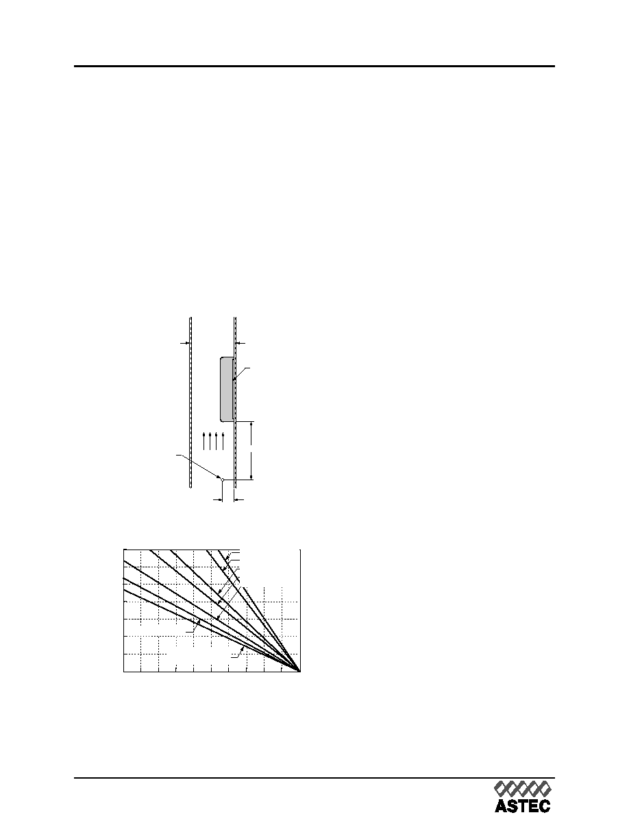
Module Derating
Experiment Setup
From the experimental set up shown in figure
31, the derating curves as figure 32 can be
drawn. Note that the PWB ( printed-wiring
board ) and the module must be mounted verti-
cally. The passage has a rectangular cross-
section. The clearance between the facing
PWB and the top of the module is kept 13 mm
(0.5 in.) constantly.
Convection W
Convection Without Heat Sinks
ithout Heat Sinks
Heat transfer can be enhanced by increasing
the airflow over the module. Figure 32 shows
the maximum power that can be dissipated by
the module.
In the test, natural convection airflow was mea-
sured at 0.05 m/s to 0.1 m/s (10 ft./min. to 20
ft./min.). The 0.5 m/s to 4.0 m/s (100 ft./min. to
800 ft./min.) curves are tested with externally
adjustable fans. The appropriate airflow for a
given operating condition can be determined
through figure 32.
Example 1. How to calculate the minimum
airflow required to maintain a desired Tc?
If a AEH20A24N module operates with a 24V
line voltage, a 20 A output current, and a 40 ° C
maximum ambient temperature, What is the
minimum airflow necessary for the operating?
Determine PD ( referenced Fig.30 ) with con-
dition:
Vin = 24 V
lO = 20 A
Get: PD = 15 W
And with TA = 40 °C
Determine airflow ( Fig.32 ):
v = 1.5 m/s (300 ft./min.)
Example 2. How to calculate the maximum
output power of a module in a certain con-
vection and a max. TA?
What is the maximum power output for a
AEH20A24N operating at following conditions:
Vin = 24 V
v = 1.5 m/s (300 ft./min.)
TA = 40 °C
Determine PD ( Fig.32 )
PD = 15W
Determine IO ( Fig.30 ):
IO = 20 A
Calculate PO:
0
10
203040
100
0
21
Local Ambient Temperature, TA (°C)
Power
Dissipation
,
P
D
(W)
15
12
6
90
80
70
60
50
4.0 m/s (800 ft./min.)
0.1 m/s (20 ft./min.)
Natural Convection
1.0 m/s (200 ft./min.)
2.0 m/s (400 ft./min.)
3.0 m/s (600 ft./min.)
3
9
18
1.5 m/s (300 ft./min.)
0.5 m/s (100 ft./min.)
Fig.32 Forced Convection Power Derating
without Heat Sink
Dimensions: millimeters (inches).
AIR VELOCITY
AND AMBIENT
TEMPERATURE
MEASURED
BELOW THE
MODULE
AIRFLOW
19 (0.75)
FACING PWB
MODULE
PWB
76 (3.00)
Fig.31 Experiment Set Up
相关PDF资料 |
PDF描述 |
|---|---|
| AEH10G24-N8 | 1-OUTPUT 25 W DC-DC REG PWR SUPPLY MODULE |
| AEH10G24-N | 1-OUTPUT 25 W DC-DC REG PWR SUPPLY MODULE |
| AEH30A24-6 | 1-OUTPUT DC-DC REG PWR SUPPLY MODULE |
| AEUFB-BR1 | INTERCONNECTION DEVICE |
| BANFA-BS1 | INTERCONNECTION DEVICE |
相关代理商/技术参数 |
参数描述 |
|---|---|
| AEH10A24L | 制造商:Johnson Components 功能描述:50W, 18-36VIN, SINGLE, 5.0V@10 |
| AEH10A24N | 功能描述:DC/DC转换器 CONV DC-DC 50W 24VIN RoHS:否 制造商:Murata 产品: 输出功率: 输入电压范围:3.6 V to 5.5 V 输入电压(标称): 输出端数量:1 输出电压(通道 1):3.3 V 输出电流(通道 1):600 mA 输出电压(通道 2): 输出电流(通道 2): 安装风格:SMD/SMT 封装 / 箱体尺寸: |
| AEH10A48 | 功能描述:DC/DC转换器 CONV DC-DC 50W 48VIN RoHS:否 制造商:Murata 产品: 输出功率: 输入电压范围:3.6 V to 5.5 V 输入电压(标称): 输出端数量:1 输出电压(通道 1):3.3 V 输出电流(通道 1):600 mA 输出电压(通道 2): 输出电流(通道 2): 安装风格:SMD/SMT 封装 / 箱体尺寸: |
| AEH10A48N | 功能描述:DC/DC转换器 CONV DC-DC 50W 48VIN RoHS:否 制造商:Murata 产品: 输出功率: 输入电压范围:3.6 V to 5.5 V 输入电压(标称): 输出端数量:1 输出电压(通道 1):3.3 V 输出电流(通道 1):600 mA 输出电压(通道 2): 输出电流(通道 2): 安装风格:SMD/SMT 封装 / 箱体尺寸: |
| AEH10F24 | 功能描述:DC/DC转换器 CONV DC-DC 50W 24VIN RoHS:否 制造商:Murata 产品: 输出功率: 输入电压范围:3.6 V to 5.5 V 输入电压(标称): 输出端数量:1 输出电压(通道 1):3.3 V 输出电流(通道 1):600 mA 输出电压(通道 2): 输出电流(通道 2): 安装风格:SMD/SMT 封装 / 箱体尺寸: |
发布紧急采购,3分钟左右您将得到回复。