- 您现在的位置:买卖IC网 > PDF目录57935 > ANCH100-200X1000G 0 MHz - 4000 MHz 100 ohm RF/MICROWAVE TERMINATION PDF资料下载
参数资料
| 型号: | ANCH100-200X1000G |
| 元件分类: | 终端器 |
| 英文描述: | 0 MHz - 4000 MHz 100 ohm RF/MICROWAVE TERMINATION |
| 封装: | ROHS COMPLIANT PACKAGE-2 |
| 文件页数: | 1/1页 |
| 文件大小: | 64K |
| 代理商: | ANCH100-200X1000G |
GENERAL INFORMATION
When mounted on an appropriate heat sink, these chip devices
provide high power dissipation in terminations and as balancing
resistors in Wilkinson power divider networks. Laser trimming
provides maximum RF power capability. Aluminum nitride
is used for those applications where the use and disposal of
beryllium oxide is a concern.
ORDERING INFORMATION
SERIES ANC
RESISTORS, TERMINATIONS
High Power Chip, Aluminum Nitride – 50 & 100 Ohms
KEY: Inches [Millimeters] .XX ±.03 .XXX ±.010 [.X ±0.8 .XX ±0.25]
NOTES
1. Resistance value is expressed using military 4-digit call-out.
50R0 = 50 Ohms
1000 = 100 Ohms
Other values from 10–500 Ohms may be available as special order.
Contact factory for availability.
2. Tinning with Sn96 “Lead Free” high temperature solder will maintain RoHS
compliance.
GENERAL SPECIFICATIONS
Solderable Terminals
Electroplated Silver over Nickel
Substrate
Aluminum Nitride
Resistive Element
Thin Film
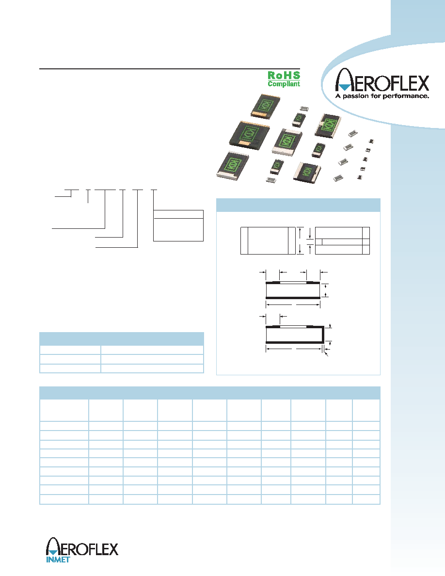
PHYSICAL DIMENSIONS
TOP
VIEW
W
B
T
L
B
TYPE X
(RESISTOR)
T
L
B
TYPE G
(TERMINATION)
50 Ohms
or
100 Ohms
50 Ohms
ONLY
0.005
[0.13]
MAX
A
(FULL FILM)
(NARROW FILM)
EXAMPLE: Typical Model No.
NPC
T 250-250
X
J
Prefix
Tinning (See Note 2)
Size
Terminal type (X or G)
Ohmic Value (Note 1)
50R0
or
1000
ANC
X
Tolerance Key
F= 1%
G = 2%
J = 5% (Standard)
(See Note 1 Below)
H = Sn96
T = Sn63
Capacitance
Termination
W
L
T
A
B
(pF)
VSWR
Power
FREQ.
Model Prefix
in
[mm]
in
[mm]
in
[mm]
in
[mm]
in
[mm]
Typical
CW
GHz
ANC 50-50
0.050
[1,27] 0.050
[1,27] 0.010 [0,25]
N/A
0.010 [0,25]
0.5
1.25
5
DC-4.0
ANC 50-100
0.050
[1,27] 0.100
[2,5]
0.010 [0,25]
N/A
0.020 [0,51]
1.0
1.25
10
DC-2.0
ANC 100-200
0.100
[2,5] 0.200
[5,1]
0.040 [1,02]
N/A
0.030 [0,76]
1.0
1.25
10
DC-4.0
ANC 200-200
0.200
[5,1]
0.200
[5,1]
0.040 [1,02] 0.085
[2,2]
0.040 [1,02]
1.2
1.25
30
DC-4.0
ANC 250-250-40
0.250
[6,4]
0.250
[6,4] 0.040 [1,02] 0.085
[2,2]
0.050 [1,27]
1.0
1.15
40
DC-2.5
ANC 250-250-80
0.250
[6,4]
0.250
[6,4] 0.040 [1,02]
N/A
0.050 [1,27]
1.6
1.25
80
DC-1.0
ANC 250-375
0.250
[6,4]
0.375
[9,5] 0.040 [1,02]
N/A
0.050 [1,27]
4.5
1.25
125
DC-1.0
ANC 350-225
0.350
[8,9]
0.225
[5,7]
0.040 [1,02] 0.045
[1,14] 0.050 [1,27]
1.4
1.25
100
DC-2.0
ANC 375-375
0.375
[9,5]
0.375
[9,5] 0.040 [1,02] 0.250
[6,4]
0.050 [1,27]
4.5
1.25
200
DC-1.0
PERFORMANCE SPECIFICATIONS
REV 04/11
300 Dino Drive, Ann Arbor, MI 48103
Tel: 888-244-6638 or 734-426-5553 Fax: 734-426-5557
www.aeroflex.com/inmet inmetsales@aeroflex.com
相关PDF资料 |
PDF描述 |
|---|---|
| ANCH100-200X1000J | 0 MHz - 4000 MHz 100 ohm RF/MICROWAVE TERMINATION |
| ANCT250-250-80X1000F | 0 MHz - 1000 MHz 100 ohm RF/MICROWAVE TERMINATION |
| ANCT250-250-80X1000G | 0 MHz - 1000 MHz 100 ohm RF/MICROWAVE TERMINATION |
| ANCT250-250-80X1000J | 0 MHz - 1000 MHz 100 ohm RF/MICROWAVE TERMINATION |
| ANCT250-375X50R0F | 0 MHz - 1000 MHz 50 ohm RF/MICROWAVE TERMINATION |
相关代理商/技术参数 |
参数描述 |
|---|---|
| AN-CIRC860960-1 | 制造商:3M (formerly Sirit, Inc.) 功能描述:860 960 MHz RHCP Antenna, Bulk |
| ANCL11G57SAA165RD3 | 制造商:Murata Manufacturing Co Ltd 功能描述: 制造商:Murata Manufacturing Co Ltd 功能描述:DIELECTRIC ANTENNAS CHIP 1.57GHZ - Tape and Reel |
| ANCL11G57SAA171RD5 | 制造商:Murata Manufacturing Co Ltd 功能描述: |
| ANCV11G57SAA128RD3 | 功能描述:天线 2MHz 50ohm 1W Chip Antenna RoHS:否 制造商:Molex 技术类型:Cellular Antenna 频率: 带宽: 尺寸:106.7 mm L x 13 mm W |
| ANCV11G57SAA144TT1 | 功能描述:天线 2MHz 50ohm 1W Chip Antenna RoHS:否 制造商:Molex 技术类型:Cellular Antenna 频率: 带宽: 尺寸:106.7 mm L x 13 mm W |
发布紧急采购,3分钟左右您将得到回复。