- 您现在的位置:买卖IC网 > PDF目录57956 > ASDX015D44D-DO (HONEYWELL SENSING AND CONTROL) DIFFERENTIAL, PEIZORESISTIVE PRESSURE SENSOR, 0-15Psi, 2%, 19A-E66, RECTANGULAR, THROUGH HOLE MOUNT PDF资料下载
参数资料
| 型号: | ASDX015D44D-DO |
| 厂商: | HONEYWELL SENSING AND CONTROL |
| 元件分类: | 压力传感器 |
| 英文描述: | DIFFERENTIAL, PEIZORESISTIVE PRESSURE SENSOR, 0-15Psi, 2%, 19A-E66, RECTANGULAR, THROUGH HOLE MOUNT |
| 封装: | DIP-8 |
| 文件页数: | 2/4页 |
| 文件大小: | 221K |
| 代理商: | ASDX015D44D-DO |
ASDX DO Series
2
www.honeywell.com/sensing
TABLE 1. GENERAL SPECIFICATIONS
Characteristic
Parameter
Characteristic
Parameter
Supply voltage (Vs)
(1)
4.75 Vdc to 5.25 Vdc
Compensated temp. range 0 °C to 85 °C [32 °F to 185 °F]
Maximum supply voltage
(1)
6.50 Vdc (max.)
Operating temp. range
-20 °C to 105 °C [-4 °F to 221 °F]
Consumption current
6 mA (typ.)
Storage temp. range
-40 °C to 125 °C [-40 °F to 257 °F]
Output current (sink)
2 mA (max.)
Vibration
10 g at 20 Hz to 2000 Hz
Output current (source)
2 mA (max.)
Shock
100 g for 11 ms
Lead soldering temperature
2 s to 4 s at 250
°C [482 °F]
Life
1 million cycles minimum
Note:
1. The sensor is not reverse polarity protected. Incorrect application of excitation voltage or ground to the wrong pin can cause electrical failure. Application of supply
voltage above the maximum can cause electrical failure.
TABLE 2. PERFORMANCE CHARACTERISTICS
Characteristic
Symbol
Min.
Typ.
Max.
Unit
Note
4R DO
1, 2
Zero pressure offset
Hoff
158
19A
1DB
counts hex
–
Full scale span (FSS)
Hfss
–
CCC
–
counts hex
3
Output at full scale pressure
Hfso
E25
E66
EA8
counts hex
–
Accuracy
–
±2.0
%H full scale
4
Response time
–
8
11
ms
5
4R DO
1, 2
Zero pressure offset
Hoff
7BE
800
841
counts hex
–
Full scale span (FSS)
Hfss
–
CCC
–
counts hex
3
Output at full scale pressure (P2)
Hfso
E25
E66
EB8
counts hex
6
Output at full scale pressure (P1)
Hfso
158
19A
1DB
counts hex
6
Accuracy
–
±2.0
% FSS
4
Output resolution
–
12
–
bit
–
Response time
–
8
11
ms
5
Notes:
1. Reference conditions (unless otherwise noted): supply voltage, V
S=5.0 ±0.01 Vdc, Ta=25 °C [77 °F].
2. Read operation: Start, Slave Address, R/W =1, Data Byte 1 (MSB), Ackn Bit, Data Byte 2 (LSB). The output is corrected pressure as unsigned 12 bits. Slave Address
is F0h. Acknowledge Bit - pull data line LOW, master generates an extra clock pulse for this purpose.
3. Span is the algebraic difference between the output voltage at the specified high pressure and the output at lowest pressure. Span is ratiometric to the supply voltage.
4. Accuracy is the combined errors from offset and span calibration, linearity, pressure hysteresis, and temperature effects. Calibration errors include the deviation of
offset and full scale from nominal values Linearity is the measured deviation based on a straight line. Hysteresis is the maximum output difference at any point within
the operating pressure range for increasing and decreasing pressure and temperature.
5. Response time for 0 PSI to full scale pressure step change, 10% to 90% rise time.
6. Sensor output when maximum positive pressure is applied on the back side (P2) or the front side (P1) of the sensing element.
TABLE 3. PRESSURE RANGE SPECIFICATIONS
Catalog Listing
Pressure Range
Burst Pressure
(1)
ASDX001xxxx-DO
0 psi to 1 psi
5 psi
ASDX005xxxx-DO
0 psi to 5 psi
20 psi
ASDX015xxxx-DO
0 psi to 15 psi
30 psi
ASDX030xxxx-DO
0 psi to 30 psi
60 psi
Note:
1. If maximum burst pressure is exceeded, even momentarily, the package may leak or burst, or the pressure sensing die may fracture.
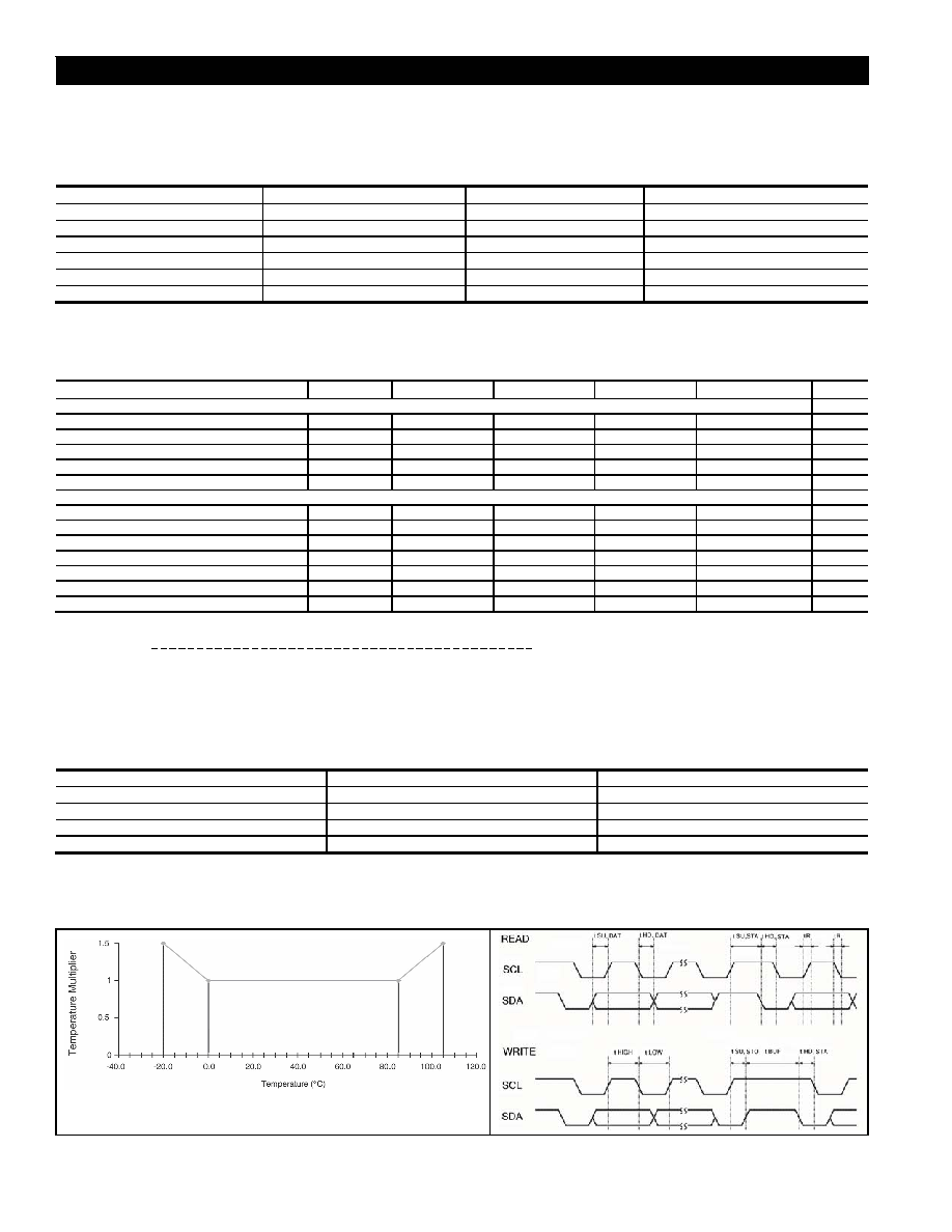
FIGURE 1. PERFORMANCE CHARACTERISTICS
(Error Band Multiplier Over -20 °C to 105 °C [-4 °F to 221 °F])
FIGURE 2. SERIAL INTERFACE TIMING CHARACTERISTICS
相关PDF资料 |
PDF描述 |
|---|---|
| ASDX001D44D-DO | DIFFERENTIAL, PEIZORESISTIVE PRESSURE SENSOR, 0-1Psi, 2%, 19A-E66, RECTANGULAR, THROUGH HOLE MOUNT |
| ASDX001G24R | GAGE, PEIZORESISTIVE PRESSURE SENSOR, 0-1Psi, 2%, 0.50-4.50V, RECTANGULAR, THROUGH HOLE MOUNT |
| ASDX015D44R | DIFFERENTIAL, PEIZORESISTIVE PRESSURE SENSOR, 0-15Psi, 2%, 0.50-4.50V, RECTANGULAR, THROUGH HOLE MOUNT |
| ASDX030D44R | DIFFERENTIAL, PEIZORESISTIVE PRESSURE SENSOR, 0-30Psi, 2%, 0.50-4.50V, RECTANGULAR, THROUGH HOLE MOUNT |
| ASDX100D44D | DIFFERENTIAL, PEIZORESISTIVE PRESSURE SENSOR, 0-100Psi, 2%, 0.50-4.50V, RECTANGULAR, THROUGH HOLE MOUNT |
相关代理商/技术参数 |
参数描述 |
|---|---|
| ASDX015D44H | 制造商:未知厂家 制造商全称:未知厂家 功能描述:0 TO 1 PSI THROUGH 0 TO 100 PSI PRESSURE TRANSDUCERS SenSym ICT |
| ASDX015D44M | 制造商:未知厂家 制造商全称:未知厂家 功能描述:0 TO 1 PSI THROUGH 0 TO 100 PSI PRESSURE TRANSDUCERS SenSym ICT |
| ASDX015D44R | 功能描述:板上安装压力/力传感器 0 to 15Psi Diff Gauge 8-Pin PDIP-D4 RoHS:否 制造商:Honeywell 工作压力:0 bar to 4 bar 压力类型:Gage 准确性:+ / - 0.25 % 输出类型:Digital 安装风格:Through Hole 工作电源电压:5 V 封装 / 箱体:SIP 端口类型:Dual Radial Barbed, Same sides |
| ASDX015D44R | 制造商:Honeywell Sensing and Control 功能描述:Pressure Sensor Operating Pressure Max:1 |
| ASDX015D44R-A | 制造商:SENSORTECHNICS 制造商全称:Sensortechnics GmbH 功能描述:Signal conditioned high precision pressure transducers |
发布紧急采购,3分钟左右您将得到回复。