- 您现在的位置:买卖IC网 > PDF目录125315 > ASDXL10D44R-DO (HONEYWELL SENSING AND CONTROL) DIFFERENTIAL, PEIZORESISTIVE PRESSURE SENSOR, 0-0.361Psi, 2.5%, RECTANGULAR, THROUGH HOLE MOUNT PDF资料下载
参数资料
| 型号: | ASDXL10D44R-DO |
| 厂商: | HONEYWELL SENSING AND CONTROL |
| 元件分类: | 压力传感器 |
| 英文描述: | DIFFERENTIAL, PEIZORESISTIVE PRESSURE SENSOR, 0-0.361Psi, 2.5%, RECTANGULAR, THROUGH HOLE MOUNT |
| 文件页数: | 2/4页 |
| 文件大小: | 506K |
| 代理商: | ASDXL10D44R-DO |
ASDXL DO Series
0 in to
±5 in H
2O, 0 in to 10 in H2O, 0 in to ±10 in H2O
2
www.honeywell.com/sensing
GENERAL SPECIFICATIONS
Characteristic
Parameter
Characteristic
Parameter
Supply voltage (Vs)
4.75 Vdc to 5.25 Vdc
Lead soldering temperature
4 s at 250
°C [482 °F]
Maximum supply voltage
6.50 Vdc max.
Vibration
10 g at 20 Hz to 2000 Hz
Current consumption
6 mA typ.
Shock
100 g for 11 ms
Output current - sink
2 mA max.
Life
1 million cycles min.
Output current - source
2 mA max.
Position sensitivity
50
V/V/g typical
ENVIRONMENTAL SPECIFICATIONS
PRESSURE RANGE SPECIFICATIONS
Characteristic
Range
Listing
Pressure Range
Burst Pressure (1)
Compensated
0
°C to 85 °C [32 °F to 185 °F]
ASDXL05
0 in to
±5 in H
20
3 PSI
Operating
-20
°C to 105 °C [-4 °F to 221 °F]
Storage
-40
°C to 125 °C [-40 °F to 257 °F]
ASDXL10
0 in to 10 in H
20
0 in to
±10 H
20
3 PSI
PERFORMANCE CHARACTERISTICS 4D DO
(2,3)
Characteristic
Min.
Typ.(5)
Max.
Unit
Full scale span (FSS)
(4,5)
–
CCC
–
counts hex
Zero pressure offset
(5)
07AE
0800
0851
counts hex
Output at full scale pressure (P2)
(5,6)
0E14
0E66
0EB8
counts hex
Output at full scale pressure (P1)
(5,6)
0147
019A
01EB
counts hex
Accuracy
(7)
–
±2.5
% FSS
Output resolution
–
12
–
bit
Response time
(8)
–
8
11
ms
PERFORMANCE CHARACTERISTICS 4R DO
(2,3)
Characteristic
Min.
Typ.
Max.
Unit
Full scale span (FSS)
(4,5)
–
CCC
–
counts hex
Zero pressure offset
(5)
0147
019A
01EB
counts hex
Output at full scale pressure
(5)
0E14
0E66
0EB8
counts hex
Accuracy
(7)
–
±2.5
% FSS
Output resolution
–
12
–
bit
Response time
(8)
–
8
11
ms
Notes:
1. If burst pressure is exceeded, even momentarily, the package may leak or the pressure sensing die may fracture.
2. Reference conditions (unless otherwise noted): supply voltage, VS=5.0
±0.01 Vdc, Ta=25 °C [77 °F].
3. Read operation: Start, Slave Address, R/W =1, Data Byte 1 (MSB), Ackn Bit, Data Byte 2 (LSB). The output is corrected pressure as unsigned
12 bits. Slave Address is F0h. Acknowledge Bit - pull data line LOW, master generates an extra clock pulse for this purpose.
4. Span is the algebraic difference between the output voltage at the specified pressure and the output at zero pressure.
5. Output is non-ratiometric within the supply voltage range (Vs).
6. Output of the device when maximum positive pressure is applied on the backside (P2) or the front side (P1) of the sensing element.
7. Accuracy is the combined errors from offset and span calibration, linearity, pressure hysteresis, and temperature effects. Calibration errors
include the deviation of offset and full scale from nominal values Linearity is the measured deviation based on a straight line. Hysteresis is the
maximum output difference at any point within the operating pressure range for increasing and decreasing pressure and temperature.
8. Response time for 0 PSI to full scale pressure step change, 10% to 90% rise time.
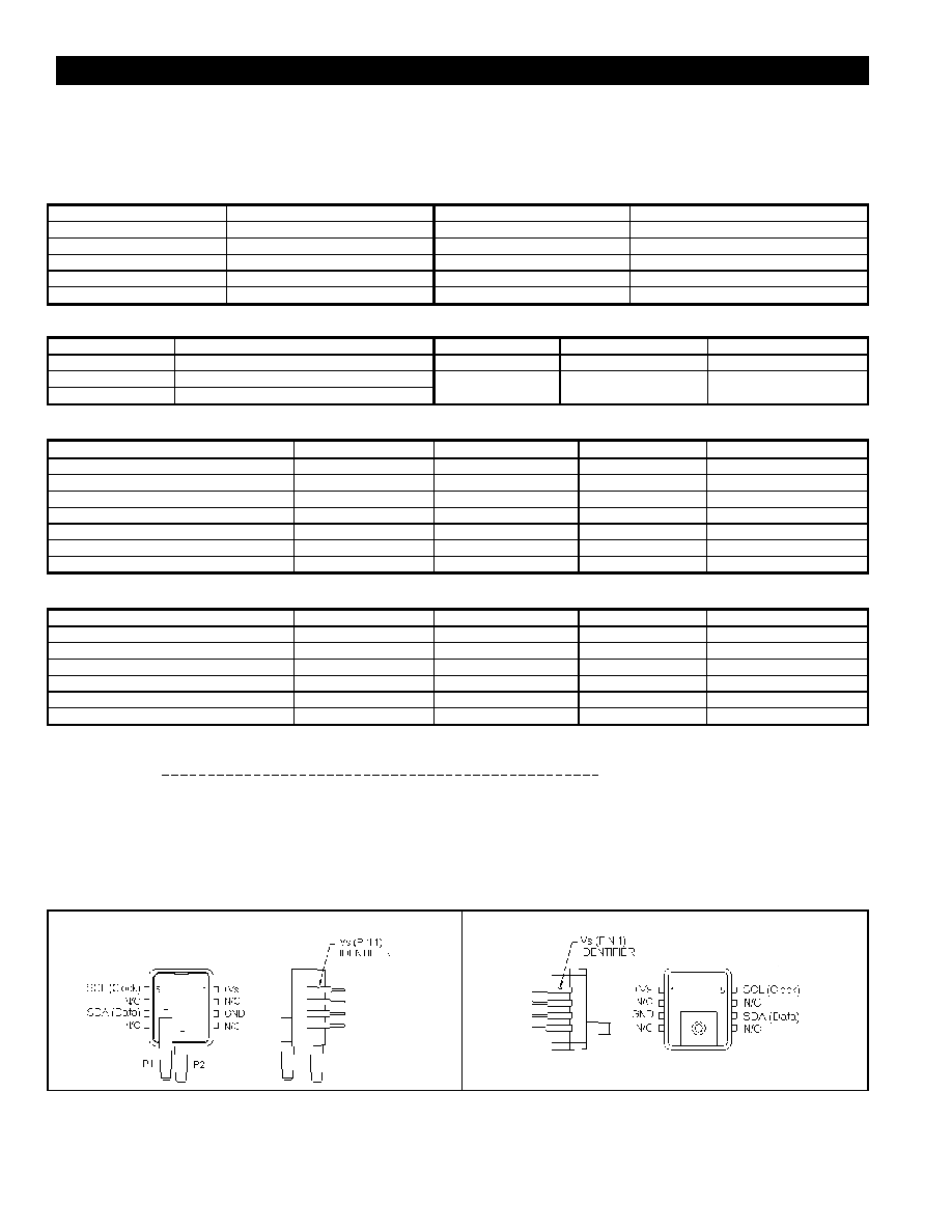
ELECTRICAL CONNECTIONS
(1,2,3)
ASDXLYYD4ZZ-DO
ASDXLYYG2ZZ-DO
Notes:
1. N/C means no connection. Connecting to ground or other potential may damage sensors.
2. Capacitor 220 nF required between +Vs and GND.
3. The sensor is not reverse polarity protected. Incorrect application of excitation voltage or ground to the wrong pin can cause electrical failure.
Application of supply voltage above the maximum can cause electrical failure.
相关PDF资料 |
PDF描述 |
|---|---|
| A1223LLHLT-T | MAGNETIC FIELD SENSOR-HALL EFFECT, -18-18mT, 30-60mA, RECTANGULAR, SURFACE MOUNT |
| A1325LLHLX-T | MAGNETIC FIELD SENSOR-HALL EFFECT, RECTANGULAR, SURFACE MOUNT |
| ADT71GN | ANALOG TEMP SENSOR-VOLTAGE, 2.5V, RECTANGULAR, THROUGH HOLE MOUNT |
| ADT71GBC | ANALOG TEMP SENSOR-VOLTAGE, 2.5V, RECTANGULAR |
| A3517SUA-LC | MAGNETIC FIELD SENSOR-HALL EFFECT, 20mT, 0.2-4.70V, RECTANGULAR, THROUGH HOLE MOUNT |
相关代理商/技术参数 |
参数描述 |
|---|---|
| ASDXL10G24R | 功能描述:板上安装压力/力传感器 4.75V to 5.25V Gauge Sensor RoHS:否 制造商:Honeywell 工作压力:0 bar to 4 bar 压力类型:Gage 准确性:+ / - 0.25 % 输出类型:Digital 安装风格:Through Hole 工作电源电压:5 V 封装 / 箱体:SIP 端口类型:Dual Radial Barbed, Same sides |
| ASDXL10G24R-DO | 功能描述:板上安装压力/力传感器 4.75V to 5.25V Gauge Sensor RoHS:否 制造商:Honeywell 工作压力:0 bar to 4 bar 压力类型:Gage 准确性:+ / - 0.25 % 输出类型:Digital 安装风格:Through Hole 工作电源电压:5 V 封装 / 箱体:SIP 端口类型:Dual Radial Barbed, Same sides |
| ASDXRRX001BAAA3 | 制造商:HONEYWELL 制造商全称:Honeywell Solid State Electronics Center 功能描述:ASDX Series Silicon Pressure Sensors |
| ASDXRRX001BAAA5 | 制造商:HONEYWELL 制造商全称:Honeywell Solid State Electronics Center 功能描述:ASDX Series Silicon Pressure Sensors |
| ASDXRRX001BAAB3 | 制造商:HONEYWELL 制造商全称:Honeywell Solid State Electronics Center 功能描述:ASDX Series Silicon Pressure Sensors |
发布紧急采购,3分钟左右您将得到回复。