- 您现在的位置:买卖IC网 > PDF目录235964 > ASFL2FREQ-L-J-S-T (ABRACON CORP) CRYSTAL OSCILLATOR, CLOCK, 1.544 MHz - 110 MHz, LVHCMOS OUTPUT PDF资料下载
参数资料
| 型号: | ASFL2FREQ-L-J-S-T |
| 厂商: | ABRACON CORP |
| 元件分类: | XO, clock |
| 英文描述: | CRYSTAL OSCILLATOR, CLOCK, 1.544 MHz - 110 MHz, LVHCMOS OUTPUT |
| 文件页数: | 1/1页 |
| 文件大小: | 176K |
| 代理商: | ASFL2FREQ-L-J-S-T |
Rev -
6/2003
Frequency Range
(Fo)
30.0MHz
Operating Temperature
(TOPR)
-10°C to +70°C (See Options)
Storage Temperature
(TSTO)
-50°C to +125°C
Frequency Stability
(
F/ Fo)
±100ppm max. (See Options)
Supply Voltage
(Vdd)
1.8 vDc ±5%
Input Current
(Idd)
6mA typ., 12mA max for F=50MHz with 15pF load
9mA typ., 18mA max for F=50MHz with 15pF load
Duty Cycle or Symmetry
40 / 60% max. (See Options)
Rise and Fall Times
(TR / TF)
3.5ns max.
Output Load
15pF
Output Voltage
(VOH)
“1” 0.9 * Vdd min.
(VOL)
“0” 0.1 * Vdd max.
Tri-State Function
“1” or Open: Oscillation
>1.6V
“0”:Output disabled (Hi Z)
<0.8V
Start-up Time
10ms max.
Aging per Year
±5ppm @ 25°C
Disable current
( Idis )
15 A typ.
Jitter one sigma RMS
±25ps max.
2.5Vdc LVHCMOS CERAMIC SURFACE MOUNT
CRYSTAL CLOCK OSCILLATORS
ASFL2
APPLICATIONS:
CCD clock for VTR camera.
Equipment connected to PC or PC cards.
Thin equipment.
FEATURES:
Compact and low in height.(1.6 mm max.)
Suitable for high density SMT., Reflow capable.
Low current consumption.
Tight stability option.
Tri state function.
Seam sealed package.
PARAMETERS
SPECIFICATIONS
S
ST
TA
AN
ND
DA
AR
RD
D S
SP
PE
EC
CIIF
FIIC
CA
AT
TIIO
ON
NS
S
Frequency Range
(Fo)
1.544MHz to 110.0MHz
Operating Temperature
(TOPR)
-10°C to +70°C (See Options)
Storage Temperature
(TSTO)
-50°C to +125°C
Frequency Stability
(
F/ Fo)
±100ppm max. (See Options)
Supply Voltage
(Vdd)
2.5 Vdc ±5%
Input Current
(Idd)
15mA max for F <50MHz
2.5mA max for F >50MHz
Duty Cycle or Symmetry
40 / 60% max. (See Options)
Rise and Fall Times
(TR / TF)
4ns max.
Output Load
15pF max.
Output Voltage
(VOH)
“1” 0.9 * Vdd min.
(VOL)
“0” 0.1 * Vdd max.
Tri-State Function
“1” or Open: Oscillation
>1.6V
“0”:Output disabled (Hi Z)
<0.8V
Start-up Time
10ms max.
Aging per Year
±5ppm @ 25°C
Disable current
( Idis )
15 A typ.
Jitter one sigma RMS
±25ps max.
ASFL2- Frequency - Temperature - Overall Frequency Stability - Duty Cycle - Packaging
XX.XXXXX MHz
-J for ± 20ppm max.*
-R for ± 25ppm max.*
-K for ± 30ppm max.*
-H for ± 35ppm max.*
-B for ± 40ppm max.
-C for ± 50ppm max.
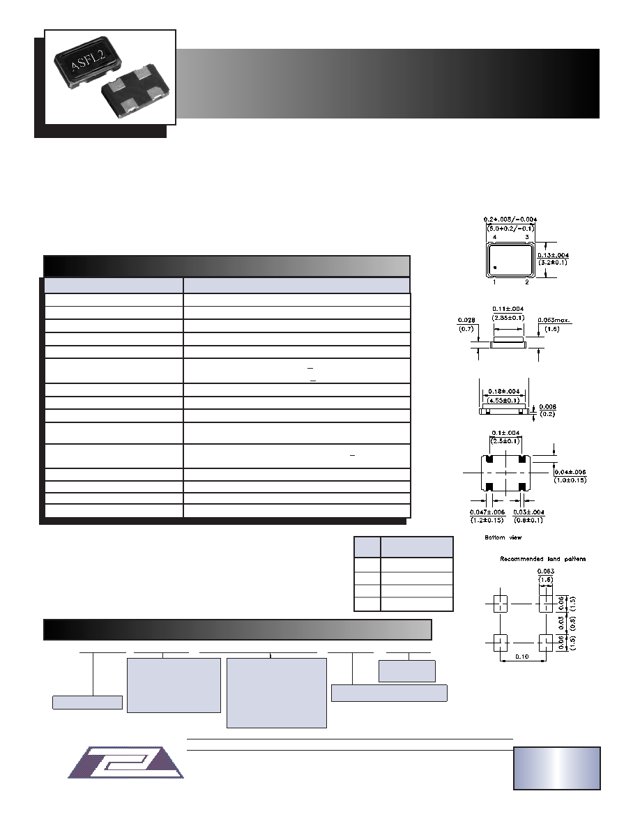
PIN
FUNCTION
N0.
1
Tri State
2
GND / Case
3
Output
4Vdd
-T
(Tape & Reel)
-S for 45 / 55% @ 1
/2 Vdd
Connect a By-Pass capacitor 0.01
F between Vdd and GND.
Environmental, and mechanical specifications, see appendix C. Group 2.
Marking, see appendix G. Test circuit, waveforms, see appendix B.
Tape and Reel, see appendix H.(1,000 pcs/reel).
Reflow profile, see appendix E.
Application notes, see appendix A.
* Vary with frequency and temperature.
Dimensions: Inches (mm)
5.0 x 3.2 x 1.6 mm
- E for -20°C to + 70°C
- F for -30°C to + 70°C
- N for -30°C to + 85°C
- L for -40°C to + 85°C
O
OR
RD
DE
ER
RIIN
NG
G O
OP
PT
TIIO
ON
NS
S
ABRACON IS
ISO 9001 / QS 9000
CERTIFIED
NOTE: Left blank if standard All specifications and markings subject to change without notice
29 Journey Aliso Viejo, CA 92656 USA
(949) 448-7070
FAX: (949) 448-8484
E-MAIL:
abinfo@ abracon.com INTERNET ADDRESS: www.abracon.com
ABRACON IS
ISO 9001 / QS 9000
CERTIFIED
ABRACON
CORPORA TION
相关PDF资料 |
PDF描述 |
|---|---|
| ASSM-FREQ13-E-C-D3-T | CRYSTAL OSCILLATOR, CLOCK, 32 MHz - 40 MHz, HCMOS/LSTTL OUTPUT |
| ASSM-FREQ13-F-H-C2-T | CRYSTAL OSCILLATOR, CLOCK, 32 MHz - 40 MHz, HCMOS/LSTTL OUTPUT |
| ASSM-FREQ13-N-K-D4-T | CRYSTAL OSCILLATOR, CLOCK, 32 MHz - 40 MHz, HCMOS/LSTTL OUTPUT |
| ASL-FREQ-N-K-S1-25-T-OUT29 | CRYSTAL OSCILLATOR, CLOCK, 1.544 MHz - 100 MHz, HCMOS/TTL OUTPUT |
| ASL-FREQ-N-R-S-25-T-OUT29 | CRYSTAL OSCILLATOR, CLOCK, 1.544 MHz - 100 MHz, HCMOS/TTL OUTPUT |
相关代理商/技术参数 |
参数描述 |
|---|---|
| ASFL3 | 制造商:ABRACON 制造商全称:Abracon Corporation 功能描述:1.8V LVHCMOS COMPATIBLE SMD COMPATIBLE SMD |
| ASFL3_08 | 制造商:ABRACON 制造商全称:Abracon Corporation 功能描述:1.8V LVHCMOS COMPATIBLE SMD COMPATIBLE SMD |
| ASFL3-1.8432MHZ-EK-T | 功能描述:标准时钟振荡器 1.8432MHZ 1.8V 30ppm RoHS:否 制造商:AVX 产品:Standard Clock Oscillators 封装 / 箱体:7 mm x 5 mm 频率:75 MHz 频率稳定性:50 PPM 电源电压:2.5 V 负载电容: 端接类型:SMD/SMT 最小工作温度:0 C 最大工作温度:+ 70 C 输出格式:LVDS 尺寸: 封装:Reel 系列: |
| ASFL3-10.000MHZ-EK | 制造商:Abracon Corporation 功能描述:XO SMD 1.8V 10.000MHz 3.2x5mm |
| ASFL3-10.000MHZ-EK-T | 功能描述:标准时钟振荡器 10.000MHZ 1.8V 30ppm RoHS:否 制造商:AVX 产品:Standard Clock Oscillators 封装 / 箱体:7 mm x 5 mm 频率:75 MHz 频率稳定性:50 PPM 电源电压:2.5 V 负载电容: 端接类型:SMD/SMT 最小工作温度:0 C 最大工作温度:+ 70 C 输出格式:LVDS 尺寸: 封装:Reel 系列: |
发布紧急采购,3分钟左右您将得到回复。