- 您现在的位置:买卖IC网 > PDF目录92929 > AT-242 500 MHz - 2000 MHz RF/MICROWAVE VARIABLE ATTENUATOR, 1.9 dB INSERTION LOSS-MAX PDF资料下载
参数资料
| 型号: | AT-242 |
| 元件分类: | 衰减器 |
| 英文描述: | 500 MHz - 2000 MHz RF/MICROWAVE VARIABLE ATTENUATOR, 1.9 dB INSERTION LOSS-MAX |
| 封装: | PLASTIC, SOIC-8 |
| 文件页数: | 1/2页 |
| 文件大小: | 66K |
| 代理商: | AT-242 |
Digital Attenuator, 3 Bit, Single Control, 28 dB, 0.5 - 2 GHz
AT-242
M/A-COM Division of AMP Incorporated
3 North America: Tel. (800) 366-2266, Fax (800) 618-8883 3 Asia/Pacific: Tel.+85 2 2111 8088, Fax +85 2 2111 8087
3 Europe: Tel. +44 (1344) 869 595, Fax+44 (1344) 300 020
www.macom.com
AMP and Connecting at a Higher Level are trademarks.
Specifications subject to change without notice.
V2.00
Features
Single Control CMOS Logic for each bit
Positive Supply +3 to +5 Volts
Low Cost SOIC-8 Plastic Package
Tape and Reel Packaging Available
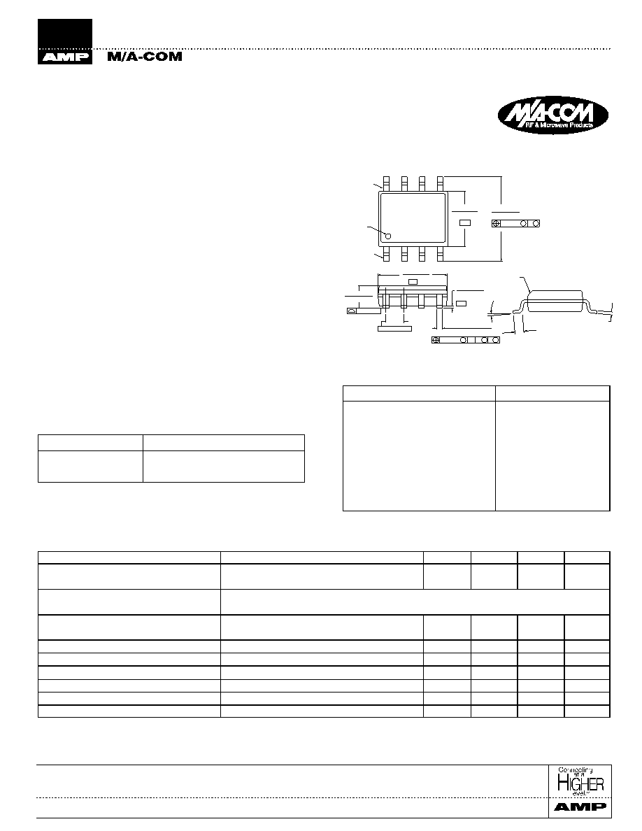
SOIC-8
1
Electrical Specifications: T
A = +25°C
1, 2
Digital Attenuator, 3 Bit, Single Control
28 dB, 0.5 - 2 GHz
AT-242
Parameter
Test Conditions
Units
Min.
Typ.
Max.
Reference Insertion Loss
0.5 - 1.0 GHz
dB
1.4
1.6
0.5 - 2.0 GHz
dB
1.7
1.9
Attenuation Accuracy
0.5 - 1.0 GHz
± (0.15 dB +3% of Attenuation Setting in dB) dB
0.5 - 2.0 GHz
± (0.3 dB = +8% of Attenuation Setting in dB) dB
VSWR
0.5 - 1.0 GHz
1.3:1
±0.8
0.5 - 2.0 GHz
1.6:1
±1.5
P
1dB
Input Power (Vs = +5V) 900 MHz
dBm
25
T
rise, Tfall
10% to 90% RF, 90% to 10% RF
S
290
T
on, Toff
50% Control to 90% RF, Control to 10% RF
S
300
Transients
In-band
mV
260
IP
2
Measured Relative to Input Power
2
dBm
75
IP
3
Measured Relative to Input Power
2
dBm
45
Description
M/A-COM’s AT-242 is a 3 bit, 4 dB step GaAs MMIC digital
attenuator in a low cost SOIC 8-lead surface mount plastic
package.
The AT-242 is ideally suited for use where high
accuracy, very low power consumption and low intermodula-
tion products are required. Typical applications include radio,
cellular, wireless LANs, GPS equipment and automatic gain/
level control circuits.
The AT-242 is fabricated with a GaAs MMIC using a mature
1-micron process. The process features full chip passivation for
increased performance and reliability.
Ordering Information
Part Number
Package
AT-242
SOIC-8 Lead Plastic
AT-242TR
Forward Tape and Reel
1
1. If specific reel size is required, consult factory for part number
assignment.
1.
All measurements at 1 GHz 5Vdc in a 50
system unless otherwise specified. The RF ports must be blocked out side of the package from
ground or any other voltage. Insertion Loss varies at 0.003 dB/°C.
2.
For two-tone input power up to +10 dBm
Parameter
Absolute Maximum
Maximum Input Power
50 MHz
+27 dBm
500 - 2000 MHz
+34 dBm
Supply Voltage
-1V, +8V
Control Voltage
-1V, Vsupply +0.5V
Operating Temperature
-40°C to +85°C
Storage Temperature
-65°C to +150°C
Absolute Maximum Ratings
1
1.
Exceeding any one or a combination of these limits may cause
permanent damage.
(.19/.25)
CHAMFER
(OPTIONAL)
(0.40/1.27)
.016/.050
0°/80°
-B-
BSC.
-C-
-A-
.010(.25)
C AB
MM
S
.050(1.27)
Oreintation
Mark
.1497/.1574
(3.80/4.00)
M
M B
.010(.25)
.2284/.2440
(5.80/6.20)
.0532/.0688
(1.35/1.75)
.004(0.10)
.0075/.0098
PIN 8
PIN 1
.013/.020 (8 PL)
(.33/.51)
.0040/.0098
(.10/.25)
.1890/.1968
(4.80/5.00)
1. Dimensions are in inches/mm.
相关PDF资料 |
PDF描述 |
|---|---|
| AT-246PIN | 0 MHz - 3000 MHz RF/MICROWAVE VARIABLE ATTENUATOR, 1 dB INSERTION LOSS-MAX |
| AT-262PIN | 0 MHz - 2000 MHz RF/MICROWAVE VARIABLE ATTENUATOR, 2.5 dB INSERTION LOSS-MAX |
| AT-264 | 500 MHz - 2000 MHz RF/MICROWAVE VARIABLE ATTENUATOR, 2.6 dB INSERTION LOSS-MAX |
| AT-266RTR | 0 MHz - 2000 MHz RF/MICROWAVE VARIABLE ATTENUATOR, 0.7 dB INSERTION LOSS-MAX |
| AT-266TR | 0 MHz - 2000 MHz RF/MICROWAVE VARIABLE ATTENUATOR, 0.7 dB INSERTION LOSS-MAX |
相关代理商/技术参数 |
参数描述 |
|---|---|
| AT2-420-24L-FT | 制造商:NK TECKNOLOGIES 功能描述:Sensor |
| AT-2428-TWT-R | 功能描述:扬声器与变频器 90 dBA 12Vpp 2800Hz RoHS:否 制造商:PUI Audio 产品:Speakers 类型:Electromagnetic 频率:900 Hz to 12 kHz 声压级:88 dBA 阻抗:8 Ohms 功率额定值:1.2 W 形状:Round 端接类型:Solder Pad 直径:15 mm 长度: 宽度: 深度:4.4 mm 磁体材料:Neodymium Iron Boran (NdFeB) 圆锥体材料:Mylar |
| AT-2429-T-LWC100-R | 制造商:PUI Audio 功能描述:- Trays |
| AT-2429-TWT-R | 功能描述:扬声器与变频器 12VP-P 8MA 70000PF RoHS:否 制造商:PUI Audio 产品:Speakers 类型:Electromagnetic 频率:900 Hz to 12 kHz 声压级:88 dBA 阻抗:8 Ohms 功率额定值:1.2 W 形状:Round 端接类型:Solder Pad 直径:15 mm 长度: 宽度: 深度:4.4 mm 磁体材料:Neodymium Iron Boran (NdFeB) 圆锥体材料:Mylar |
| AT-242-PIN | 制造商:M/A-COM Technology Solutions 功能描述:ATTENUATOR, DIGITAL, 3 BIT LSB 4DB - Bulk |
发布紧急采购,3分钟左右您将得到回复。