- 您现在的位置:买卖IC网 > PDF目录362518 > ATH12 CHOKE,AXIAL,CONFORMAL,8.2uH, 5% INDUCTIVE TOL,155 IDC, PDF资料下载
参数资料
| 型号: | ATH12 |
| 英文描述: | CHOKE,AXIAL,CONFORMAL,8.2uH, 5% INDUCTIVE TOL,155 IDC, |
| 中文描述: | 6甲,3.3 - V输入非隔离宽输出调节电源模块 |
| 文件页数: | 12/14页 |
| 文件大小: | 391K |
| 代理商: | ATH12 |
Application Notes
ATH Series of Wide-Output Adjust Power
Modules (3.3/5-V Input)
North America (USA): 1-888-41-ASTEC Europe (UK): 44(1384)842-211 Asia (HK): 852-2437-9662
Pre-Bias Startup Capability
Only selected products in the ATH family incorporate this
capability. Consult Table 3-1 to identify which products
are compliant.
A pre-bias startup condition occurs as a result of an external
voltage being present at the output of a power module prior
to its output becoming active. This often occurs in com-
plex digital systems when current from another power
source is backfed through a dual-supply logic component,
such as an FPGA or ASIC. Another path might be via
clamp diodes as part of a dual-supply power-up sequencing
arrangement. A prebias can cause problems with power
modules that incorporate synchronous rectifiers. This is
because under most operating conditions, these types of
modules can sink as well as source output current.
The ATH family of power modules incorporate synchro-
nous rectifiers, but will not sink current during startup
1
,
or whenever the
Inhibit
pin is held low. However, to ensure
satisfactory operation of this function, certain conditions
must be maintained.
2
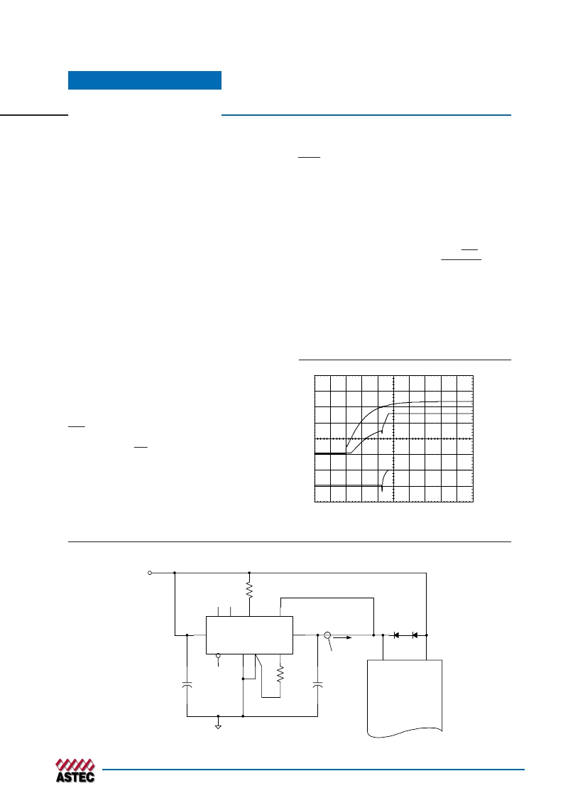
Figure 3-7 shows an application
demonstrating the pre-bias startup capability. The start-
up waveforms are shown in Figure 3-9. Note that the
output current from the ATH15T033-9xx (I
o
) shows neg-
ligible current until its output voltage rises above that
backfed through diodes D
1
and D
2
.
Note: The pre-bias start-up feature is not compatible with
Auto-Track. When the module is under Auto-Track control, it
is fully active and will sink current if the output voltage is
below that of a back-feeding source. Therefore to ensure a pre-
bias hold-off, one of two approaches must be followed when
input power is applied to the module. The Auto-Track function
must either be disabled
3
, or the module’s output held off using
the Inhibit pin. The latter allows Auto-Track’s internal (RC)
voltage ramp to rise above the set-point voltage.
Notes
1. Startup is the relatively short period (approx. 10 ms)
prior to the output voltage rising. The startup period
immediately follows either the application of a valid
input source voltage, or the release of a ground signal
at the
Inhibit
pin.
2. To ensure that the regulator does not sink current when
power is first applied (even with a ground signal applied
to the
Inhibit
control pin), the input voltage must always
be greater than the output voltage throughout the
power-up and power-down sequence.
3. The Auto-Track function can be disabled at power up
by immediately applying a voltage to the module’s
Track
pin that is greater than its set-point voltage. This can
be easily accomplished by connecting the
Track
pin to
V
in
through a 1-k
resistor.
V
o
= 2.5 V
V
IN
= 3.3 V
R
2
2k21
R
1
1k0
ASIC
VCORE
VCCIO
I
o
PTH03010W
ATH15T033-9S
1
10
4
5
6
2
3
9
8
Track
V
IN
V
O
GND
Inhibit
7
Vadj
Sense
+
C
IN
330 μF
+
D
1
, D
2
MBR3100
C
OUT
330 μF
+
Figure 3.8; Application Circuit Demonstrating Pre-Bias Startup
Vin (1 V/Div)
Vo (1 V/Div)
Io (5 A/Div)
HORIZ SCALE: 5 ms/Div
Figure 3.9; Pre-Bias Startup Waveforms
相关PDF资料 |
PDF描述 |
|---|---|
| ATH15 | CHOKE,AXIAL,CONFORMAL,0.68uH, 10% INDUCTIVE TOL,495 IDC, |
| ATH18 | 6-A, 3.3-V Input Non-Isolated Wide-Output Adjust Power Module |
| ATH22 | 6-A, 3.3-V Input Non-Isolated Wide-Output Adjust Power Module |
| ATH26 | 6-A, 3.3-V Input Non-Isolated Wide-Output Adjust Power Module |
| ATH10K12 | 10-A, 12-V Input Non-Isolated Wide-Output Adjust Power Module |
相关代理商/技术参数 |
参数描述 |
|---|---|
| ATH12K12-9 | 制造商:ASTEC 制造商全称:Astec America, Inc 功能描述:15Amps |
| ATH12K12-9J | 功能描述:DC/DC转换器 DC-DC 1OUT 1.2V-5.5V 12A 66W 10-Pin RoHS:否 制造商:Murata 产品: 输出功率: 输入电压范围:3.6 V to 5.5 V 输入电压(标称): 输出端数量:1 输出电压(通道 1):3.3 V 输出电流(通道 1):600 mA 输出电压(通道 2): 输出电流(通道 2): 安装风格:SMD/SMT 封装 / 箱体尺寸: |
| ATH12K12-9JL | 功能描述:DC/DC转换器 DC-DC 1OUT 1.2V-5.5V 12A 66W 10-Pin RoHS:否 制造商:Murata 产品: 输出功率: 输入电压范围:3.6 V to 5.5 V 输入电压(标称): 输出端数量:1 输出电压(通道 1):3.3 V 输出电流(通道 1):600 mA 输出电压(通道 2): 输出电流(通道 2): 安装风格:SMD/SMT 封装 / 箱体尺寸: |
| ATH12K12-9S | 制造商:ASTEC 制造商全称:Astec America, Inc 功能描述:15Amps |
| ATH12K12-9SJ | 功能描述:DC/DC转换器 DC-DC 1OUT 1.2V-5.5V 12A 66W 10-Pin SMT RoHS:否 制造商:Murata 产品: 输出功率: 输入电压范围:3.6 V to 5.5 V 输入电压(标称): 输出端数量:1 输出电压(通道 1):3.3 V 输出电流(通道 1):600 mA 输出电压(通道 2): 输出电流(通道 2): 安装风格:SMD/SMT 封装 / 箱体尺寸: |
发布紧急采购,3分钟左右您将得到回复。