- 您现在的位置:买卖IC网 > PDF目录375378 > ATTL7554BP-TR L7554 Low-Power SLIC PDF资料下载
参数资料
| 型号: | ATTL7554BP-TR |
| 英文描述: | L7554 Low-Power SLIC |
| 中文描述: | L7554低功耗用户接口 |
| 文件页数: | 20/28页 |
| 文件大小: | 486K |
| 代理商: | ATTL7554BP-TR |
第1页第2页第3页第4页第5页第6页第7页第8页第9页第10页第11页第12页第13页第14页第15页第16页第17页第18页第19页当前第20页第21页第22页第23页第24页第25页第26页第27页第28页
20
Lucent Technologies Inc.
Data Sheet
March 1997
L7554 Low-Power SLIC
Applications
(continued)
dc Applications
Battery Feed
The dc feed characteristic can be described by:
(
)
R
L
2R
P
Rdc
+
+
where:
I
L
= dc loop current.
V
T/R
= dc loop voltage.
|V
BAT
| = battery voltage magnitude.
V
OH
= overhead voltage. This is the difference between
the battery voltage and the open loop Tip/Ring
voltage.
R
L
= loop resistance, not including protection resistors.
R
P
= protection resistor value.
Rdc = SLIC internal dc feed resistance.
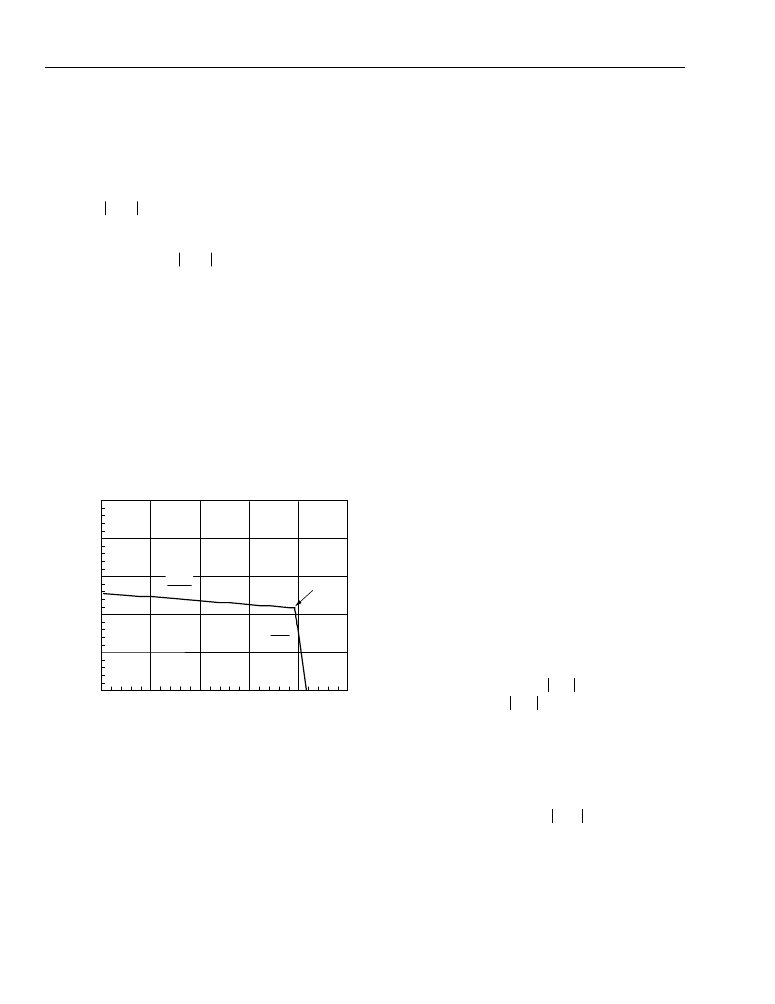
The design begins by drawing the desired dc template.
An example is shown in Figure 25.
Note: V
BAT
= –48 V; I
LIM
= 22 mA; R
DC1
= 113
.
12-3050 (C)
Figure 25. Loop Current vs. Loop Voltage
Starting from the on-hook condition and going through
to a short circuit, the curve passes through two regions:
Region 1; On-hook and low loop currents. The slope
corresponds to the dc resistance of the SLIC, R
DC1
(de-
fault is 113
typical). The open-circuit voltage is the
battery voltage less the overhead voltage of the device,
V
OH
(default is 6.5 V typical). These values are suitable
for most applications, but can be adjusted if needed. For
more information, see the sections entitled Adjusting dc
Feed Resistance and Adjusting Overhead Voltage.
Region 2; Current limit. The dc current is limited to a val-
ue determined by external resistor R
PROG
. This region of
the dc template has a high resistance (10 k
).
Calculate the external resistor as follows:
R
PROG
(k
) = 1.67 I
LIM
(mA)
Overhead Voltage
In order to drive an on-hook ac signal, the SLIC must
set up the Tip and Ring voltage to a value less than the
battery voltage. The amount that the open loop voltage
is decreased relative to the battery is referred to as the
overhead voltage. Expressed as an equation,
V
OH
= |V
BAT
| – (V
PT
– V
PR
)
Without this buffer voltage, amplifier saturation will
occur and the signal will be clipped. The 7551 is auto-
matically set at the factory to allow undistorted on-hook
transmission of a 3.17 dBm signal into a 900
loop
impedance. For applications where higher signal levels
are needed, e.g., periodic pulse metering, the 2-wire
port of the SLIC can be programmed with pin DCR.
The drive amplifiers are capable of 4 Vrms minimum
(V
AMP
). Referring to Figure 26, the internal resistance
has a worst-case value of 46
. So, the maximum sig-
nal the device can guarantee is:
Thus, R
P
≤
35
allows 2.2 Vrms metering signals. The
next step is to determine the amount of overhead volt-
age needed. The peak voltage at output of Tip and
Ring amplifiers is related to the peak signal voltage by:
V
T R
L
--------------------------------------------
=
I
L
R
L
+
Rdc
+
2R
P
----------------------------------
=
L
0
10
20
50
0
20
30
40
50
LOOP VOLTAGE (V)
30
40
10
1
10 k
I
LIM
–1
R
DC1
V
T/R
4 V
2 R
P
Z
T/R
46
+
)
+
-----------------------------------------
=
vamp = v
T/R
1
-----------------------------
+
)
Z
T R
+
Λ
Λ
相关PDF资料 |
PDF描述 |
|---|---|
| ATTL7554P-TR | L7554 Low-Power SLIC |
| ATTL7554AP | LH1263 E&M Signaling Circuit |
| AU01Z | Fast-Recovery Rectifier Diodes |
| AU02Z | Fast-Recovery Rectifier Diodes |
| AU01 | ER 3C 2#16 1#8 SKT PLUG |
相关代理商/技术参数 |
参数描述 |
|---|---|
| ATTL7554P-TR | 制造商:AGERE 制造商全称:AGERE 功能描述:L7554 Low-Power SLIC |
| ATTL7556AAU | 制造商:未知厂家 制造商全称:未知厂家 功能描述:LH1263 E&M Signaling Circuit |
| ATTL7556AAU-TR | 制造商:AGERE 制造商全称:AGERE 功能描述:Low-Power SLICs with Battery Switch |
| ATTL7557AAU | 制造商:AGERE 制造商全称:AGERE 功能描述:Low-Power SLICs with Battery Switch |
| ATTL7557AAU-TR | 制造商:AGERE 制造商全称:AGERE 功能描述:Low-Power SLICs with Battery Switch |
发布紧急采购,3分钟左右您将得到回复。