- 您现在的位置:买卖IC网 > PDF目录17410 > AUIPS7145RTRR (International Rectifier)IC SW IPS 1CH HIGH SIDE DPAK-5 PDF资料下载
参数资料
| 型号: | AUIPS7145RTRR |
| 厂商: | International Rectifier |
| 文件页数: | 6/16页 |
| 文件大小: | 0K |
| 描述: | IC SW IPS 1CH HIGH SIDE DPAK-5 |
| 标准包装: | 3,000 |
| 类型: | 高端,电流感应 |
| 输入类型: | 非反相 |
| 输出数: | 1 |
| 导通状态电阻: | 75 毫欧 |
| 电流 - 输出 / 通道: | 2.1A |
| 电流 - 峰值输出: | 25A |
| 电源电压: | 3 V ~ 5 V |
| 工作温度: | -40°C ~ 150°C |
| 安装类型: | 表面贴装 |
| 封装/外壳: | TO-252-5,DPak(4 引线 + 接片),TO-252AD |
| 供应商设备封装: | D-Pak |
| 包装: | 带卷 (TR) |
�� �
�
 �
�AUIPS7145R�
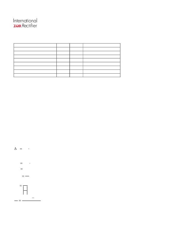
�Truth� Table�
�Op.� Conditions�
�Normal� mode�
�Normal� mode�
�Open� load�
�Open� load�
�Short� circuit� to� GND�
�Short� circuit� to� GND�
�Over� temperature�
�Over� temperature�
�Input�
�H�
�L�
�H�
�L�
�H�
�L�
�H�
�L�
�Output�
�L�
�H�
�L�
�H�
�L�
�L�
�L�
�L�
�Ifb� pin� voltage�
�0V�
�I� load� x� Rfb� /� Ratio�
�0V�
�0V�
�0V�
�V� fault� (latched)�
�0V�
�V� fault� (latched)�
�Operating� voltage�
�Maximum� Vcc� voltage� :� this� is� the� maximum� voltage� before� the� breakdown� of� the� IC� process.�
�Operating� voltage� :� This� is� the� Vcc� range� in� which� the� functionality� of� the� part� is� guaranteed.� The� AEC-Q100� qualification�
�is� run� at� the� maximum� operating� voltage� specified� in� the� datasheet.�
�Reverse� battery�
�During� the� reverse� battery� the� Mosfet� is� kept� off� and� the� load� current� is� flowing� into� the� body� diode� of� the� power� Mosfet.�
�Power� dissipation� in� the� IPS� :� P� =� I� load� *� Vf�
�There� is� no� protection,� so� Tj� must� be� lower� than� 150°C� in� the� worst� case� condition� of� current� and� ambient� temperature.�
�If� the� power� dissipation� is� too� high� in� Rifb,� a� diode� in� serial� can� be� added� to� block� the� current.�
�The� transistor� used� to� pull-down� the� input� should� be� a� bipolar� in� order� to� block� the� reverse� current.� The� 100ohm� input�
�resistor� can� not� sustain� continuously� 16V� (see� Vcc-Vin� max.� in� the� Absolute� Maximum� Ratings� section)�
�Active� clamp�
�The� purpose� of� the� active� clamp� is� to� limit� the� voltage� across� the� MOSFET� to� a� value� below� the� body� diode� break� down�
�voltage� to� reduce� the� amount� of� stress� on� the� device� during� switching.�
�The� temperature� increase� during� active� clamp� can� be� estimated� as� follows:�
�Tj�
�P� CL� Z� TH� (� t� CLAMP� )�
�Where:� Z� TH� (� t� CLAMP� )� is� the� thermal� impedance� at� t� CLAMP� and� can� be� read� from� the� thermal� impedance� curves� given� in� the�
�data� sheets.�
�P� CL�
�V� CL�
�I� CLavg�
�t� CL�
�V� CL� I� CLavg� :� Power� dissipation� during� active� clamp�
�65V� :� Typical� V� CLAMP� value.�
�I� CL� :� Average� current� during� active� clamp�
�2�
�I� CL� :� Active� clamp� duration�
�di�
�dt�
�di�
�dt�
�V� Battery�
�L�
�V� CL� :� Demagnetization� current�
�Figure� 9� gives� the� maximum� inductance� versus� the� load� current� in� the� worst� case� :� the� part� switches� off� after� an� over�
�temperature� detection.� If� the� load� inductance� exceeds� the� curve,� a� free� wheeling� diode� is� required.�
�www.irf.com�
�6�
�相关PDF资料 |
PDF描述 |
|---|---|
| M7RRK-3610K | IDC CABLE - MDK36K/MC36F/MDK36K |
| GCM08DCTD-S288 | CONN EDGECARD 16POS .156 EXTEND |
| ISL9104AIRUAEVAL1Z | EVAL BOARD 1 FOR ISL9104AIRUA |
| AUIPS7145RTRL | IC SW IPS 1CH HIGH SIDE DPAK-5 |
| GCA10DRMN-S288 | CONN EDGECARD 20POS .125 EXTEND |
相关代理商/技术参数 |
参数描述 |
|---|---|
| AUIPS72211R | 功能描述:功率驱动器IC IPS HS PWM, 75V 35A RoHS:否 制造商:Micrel 产品:MOSFET Gate Drivers 类型:Low Cost High or Low Side MOSFET Driver 上升时间: 下降时间: 电源电压-最大:30 V 电源电压-最小:2.75 V 电源电流: 最大功率耗散: 最大工作温度:+ 85 C 安装风格:SMD/SMT 封装 / 箱体:SOIC-8 封装:Tube |
| AUIPS72211RTR | 制造商:International Rectifier 功能描述:AUTO IPS D-PAK - Tape and Reel 制造商:International Rectifier 功能描述:IC PWM IPS HIGH SIDE DPAK-5 制造商:International Rectifier 功能描述:Low EMI PWR Switch 35mOhm 75V 20A |
| AUIPS72211RTRL | 功能描述:功率驱动器IC IPS HS PWM, 75V 35A RoHS:否 制造商:Micrel 产品:MOSFET Gate Drivers 类型:Low Cost High or Low Side MOSFET Driver 上升时间: 下降时间: 电源电压-最大:30 V 电源电压-最小:2.75 V 电源电流: 最大功率耗散: 最大工作温度:+ 85 C 安装风格:SMD/SMT 封装 / 箱体:SOIC-8 封装:Tube |
| AUIPS72211RTRR | 制造商:International Rectifier 功能描述:AUTO IPS D-PAK - Tape and Reel 制造商:International Rectifier 功能描述:IC PWM IPS HIGH SIDE DPAK-5 制造商:International Rectifier 功能描述:Low EMI PWR Switch 35mOhm 75V 20A |
| AUIPS7221R | 功能描述:功率驱动器IC PWM High Side PWR 100kHz 35mOhm 25A RoHS:否 制造商:Micrel 产品:MOSFET Gate Drivers 类型:Low Cost High or Low Side MOSFET Driver 上升时间: 下降时间: 电源电压-最大:30 V 电源电压-最小:2.75 V 电源电流: 最大功率耗散: 最大工作温度:+ 85 C 安装风格:SMD/SMT 封装 / 箱体:SOIC-8 封装:Tube |
发布紧急采购,3分钟左右您将得到回复。