- 您现在的位置:买卖IC网 > PDF目录1197 > AYF512415 (Panasonic Electric Works)CONN SOCKET FPC 0.5MM 24POS SMD PDF资料下载
参数资料
| 型号: | AYF512415 |
| 厂商: | Panasonic Electric Works |
| 文件页数: | 4/4页 |
| 文件大小: | 0K |
| 描述: | CONN SOCKET FPC 0.5MM 24POS SMD |
| 产品变化通告: | AYF512415 Discontinuation Feb/2012 |
| 标准包装: | 1 |
| 系列: | Y5S |
| 连接器类型: | 底部触点 |
| 位置数: | 24 |
| 间距: | 0.020"(0.50mm) |
| FFC,FCB 厚度: | 0.30mm |
| 板上方高度: | 0.075"(1.90mm) |
| 安装类型: | 表面贴装,直角 |
| 线缆端类型: | 直形 |
| 端子: | 焊接 |
| 锁定功能: | 滑锁 |
| 特点: | 固定焊尾 |
| 包装: | 标准包装 |
| 触点表面涂层: | 金 |
| 工作温度: | -55°C ~ 85°C |
| 额定电流: | 0.500A(每触点) |
| 额定电压: | 50V |
| 体座材料: | 聚酰胺(PA),尼龙 |
| 其它名称: | 255-3063-6 |
�� ��
��
��NOTES FOR USING FPC CONNECTORS� (Common)�
�PC� board� design�
�Design� the� recommended� foot� pattern� in�
�order� to� secure� the� mechanical� strength�
�in� the� soldered� areas� of� the� terminal.�
�FPC� and� equipment� design�
�Design� the� FPC� based� with�
�recommended� dimensions� to� ensure� the�
�required� connector� performance.�
�Due� to� the� FPC� size,� weight,� or� the�
�reaction� force� of� the� routed� FPC.�
�Carefully� check� the� equipment� design�
�and� take� required� measures� to� prevent�
�the� FPC� from� being� removed� due� to� a� fall,�
�?� Screen� thickness� of� 120� μ� m� is�
�recommended� for� paste� solder� printing.�
�?� Consult� us� when� using� a� screen-printing�
�thickness� other� than� that� recommended.�
�?� Depending� on� the� size� of� the� connector�
�being� used,� self� alignment� may� not� be�
�possible.� Accordingly,� carefully� position�
�the� terminal� with� the� PC� board� pattern.�
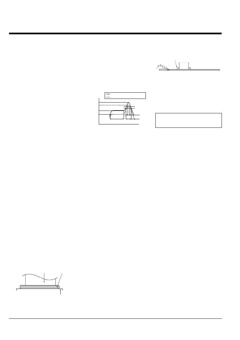
�?� The� recommended� re?ow� temperature�
�pro?le� is� given� in� the� ?gure� below�
�Recommended� re?ow� temperature�
�pro?le�
�Upper� limit� (Soldering� heat� resistance)�
�When� cutting� or� bending� the� PC�
�board� after� mounting� the� connector,�
�be� careful� that� the� soldered� sections�
�are� subjected� to� excessive� forces.�
�The� soldered� areas� should� not� be� subjected� to� forces.�
�Other� Notes�
�When� coating� the� PC� board� after�
�soldering� the� connector� (to� prevent� the�
�deterioration� of� insulation),� perform� the�
�coating� in� such� a� way� so� that� the� coating�
�vibration,� or� other� impact.�
�Connector� mounting�
�Temperature�
�260� °� C�
�Lower� limit� (Solder� wettability)�
�Peak� temperature�
�does� not� get� on� the� connector.�
�The� connectors� are� not� meant� to� be� used�
�Excessive� mounter� chucking� force� may�
�deform� the� molded� or� metal� part� of� the�
�connector.� Consult� us� in� advance� if�
�chucking� is� to� be� applied.�
�Soldering�
�1)� Manual� soldering.�
�230� °� C�
�180� °� C�
�150� °� C�
�Preheating�
�60� to� 120� sec.�
�220� °� C�
�200� °� C�
�25� sec.�
�70� sec.�
�Time�
�for� switching.�
�Please� refer� to� the� latest� product�
�speci?cations� when� designing� your�
�product.�
�?� Due� to� the� connector’s� low� pro?le,� if� an�
�excessive� amount� of� solder� is� applied�
�during� manual� soldering,� the� solder� may�
�creep� up� near� the� contact� points,� or�
�solder� interference� may� cause� imperfect�
�contact.�
�?� Make� sure� that� the� soldering� iron� tip� is�
�heated� within� the� temperature� and� time�
�limits� indicated� in� the� speci?cations.�
�?� Flux� from� the� solder� wire� may� adhere� to�
�the� contact� surfaces� during� soldering�
�operations.� After� soldering,� carefully�
�check� the� contact� surfaces� and� clean� off�
�any� ?ux� before� use.�
�?� Be� aware� that� a� load� applied� to� the�
�connector� terminals� while� soldering� may�
�displace� the� contact.�
�?� Thoroughly� clean� the� iron� tip.�
�2)� Re?ow� soldering�
�?� Screen-printing� is� recommended� for�
�printing� paste� solder.�
�?� To� determine� the� relationship� between�
�the� screen� opening� area� and� the� PC�
�board� foot� pattern� area,� refer� to� the�
�diagrams� in� the� recommended� patterns�
�for� PC� boards� and� metal� masks� when�
�setting.�
�?� Note� that� excess� solder� on� the� terminals�
�prevents� complete� insertion� of� the� FPC,�
�and� that� excess� solder� on� the� soldering�
�terminals� prevents� the� lever� from� rotating.�
�?� The� temperature� is� measured� on� the�
�surface� of� the� PC� board� near� the�
�connector� terminal.�
�?� Certain� solder� and� ?ux� types� may� cause�
�serious� solder� creeping.� Solder� and� ?ux�
�characteristics� should� be� taken� into�
�consideration� when� setting� the� re?ow�
�soldering� conditions.�
�?� When� performing� re?ow� soldering� on�
�the� back� of� the� PC� board� after� re?ow�
�soldering� the� connector,� secure� the�
�connector� using,� for� example,� an�
�adhesive.� (Double� re?ow� soldering� on� the�
�same� side� is� possible)�
�3)� Reworking� on� a� soldered� portion�
�?� Finish� reworking� in� one� operation.�
�?� For� reworking� of� the� solder� bridge,� use�
�a� soldering� iron� with� a� ?at� tip.� Do� not� add�
�?ux,� otherwise� the� ?ux� may� creep� to� the�
�contact� parts.�
�?� Use� a� soldering� iron� whose� tip�
�temperature� is� within� the� temperature�
�range� speci?ed� in� the� speci?cations.�
�Do� not� drop� or� handle� the�
�connector� carelessly.� Otherwise,� the�
�terminals� may� become� deformed� due�
�to� excessive� force� or� applied�
�solderability� may� be� during� re?ow�
�degrade.�
�Don’t� open/close� the� lever� or� insert/�
�remove� an� FPC� until� the� connector� is�
�Terminal�
�Paste� solder�
�soldered.� Forcibly� applied� external�
�pressure� on� the� terminals� can� weaken�
�the� adherence� of� the� terminals� to� the�
�molded� part� or� cause� the� terminals� to�
�lose� their� evenness.� In� addition,� do�
�not� insert� an� FPC� into� the� connector�
�PC� board� foot� pattern�
�before� soldering� the� connector.�
�Panasonic� Corporation�
�Automation� Controls� Business� Unit�
�industrial.panasonic.com/ac/e�
�ACCTB13E� 201201-T�
�相关PDF资料 |
PDF描述 |
|---|---|
| AYF522615 | CONN SOCKET FPC 0.5MM 26POS SMD |
| AYF535065 | CONN SOCKET FPC 0.5MM 50POS SMD |
| B004-004-R | SWITCH KVM PS/2-4PORT WO/CABLES |
| B004-008 | SWITCH KVM 8 PORT 1U RACK MT PS2 |
| B006-004-R | SWITCH KVM USB 4 PORT W/O CABLES |
相关代理商/技术参数 |
参数描述 |
|---|---|
| AYF522615 | 功能描述:CONN SOCKET FPC 0.5MM 26POS SMD RoHS:是 类别:连接器,互连式 >> FFC,FPC(扁平软线)- 连接器 - 面板安装 系列:Y5F 标准包装:1 系列:Easy-On™ 54809 连接器类型:底部触点 位置数:31 间距:0.012"(0.30mm) FFC,FCB 厚度:0.20mm 板上方高度:0.051"(1.30mm) 安装类型:表面贴装,直角 线缆端类型:直形 端子:焊接 锁定功能:触发锁 特点:零插入力(ZIF) 包装:Digi-Reel® 触点表面涂层:锡铋 触点涂层厚度:- 工作温度:-20°C ~ 85°C 额定电流:0.300A 额定电压:50V 体座材料:液晶聚合物(LCP) 其它名称:WM6540DKR |
| AYF522615-35K | 制造商:Panasonic Electric Works 功能描述: |
| AYF523415 | 功能描述:FFC & FPC连接器 Connector RoHS:否 制造商:JAE Electronics 产品类型:Plugs 系列:HD 节距:0.5 mm 位置/触点数量:40 安装角: 安装风格:Cable 外壳材料:Plastic 触点材料:Copper Alloy 触点电镀:Gold 电压额定值:100 V per contact 电流额定值:0.24 A to 1 A |
| AYF524015 | 功能描述:FFC & FPC连接器 FPC Connector RoHS:否 制造商:JAE Electronics 产品类型:Plugs 系列:HD 节距:0.5 mm 位置/触点数量:40 安装角: 安装风格:Cable 外壳材料:Plastic 触点材料:Copper Alloy 触点电镀:Gold 电压额定值:100 V per contact 电流额定值:0.24 A to 1 A |
| AYF524015-35K | 制造商:Panasonic Electric Works 功能描述: |
发布紧急采购,3分钟左右您将得到回复。