参数资料
| 型号: | BA00CC0WT |
| 厂商: | Rohm Semiconductor |
| 文件页数: | 12/20页 |
| 文件大小: | 0K |
| 描述: | IC REG LDO ADJ 1A TO220FP-5 |
| 标准包装: | 500 |
| 稳压器拓扑结构: | 正,可调式 |
| 输出电压: | 可调 |
| 输入电压: | 4 V ~ 25 V |
| 电压 - 压降(标准): | 0.3V @ 500mA |
| 稳压器数量: | 1 |
| 电流 - 输出: | 1A(最小值) |
| 工作温度: | -40°C ~ 125°C |
| 安装类型: | 通孔 |
| 封装/外壳: | TO-220-5 整包 |
| 供应商设备封装: | TO-220FP-5 |
| 包装: | 管件 |
�� �
�
�BA00DD0xx� series� BA00CC0xx� series�
�●� Power� Dissipation�
�HRP5�
�To225FP-5�
�TO220FP-5�
�Datasheet�
�Board� size� :� 70� ×� 70� ×� 1.6� ㎜�
�(� board� contains� a� thermal� )�
�Board� front� copper� foil� area� :� 10.5� ×� 10.5� ㎜�
�①� 2-layer� board� (back� surface� copper� foil� area� :15� ×� 15� ㎜� )�
�②� 2-layer� board� (back� surface� copper� foil� area� :70� ×� 70� ㎜� )�
�③� 4-layer� board� (back� surface� copper� foil� area� :70� ×� 70� ㎜� )�
�10�
�9�
�8�
�3�
�2�
�2�
�2�
�2�
�25�
�20�
�(� 1� )�
�(� 2� )�
�(� 1� )� 20.0�
�When� using� a� maximum� heat� sick� :� θ� j-c=6.25(� ℃� /W)�
�When� using� an� IC� alone� :� θ� j-c=62.5(� ℃� /W)�
�7�
�6�
�5�
�4�
�3�
�③� 7.3W�
�②� 5.5W�
�15�
�10�
�2�
�1�
�0�
�①� 2.3W�
�5�
�0�
�(� 2� )� 2.0�
�0�
�25�
�50� 75� 100�
�125�
�150�
�0�
�25�
�50� 75� 100�
�125�
�150�
�TO252-5�
�Ambient� temperature:Ta(℃)�
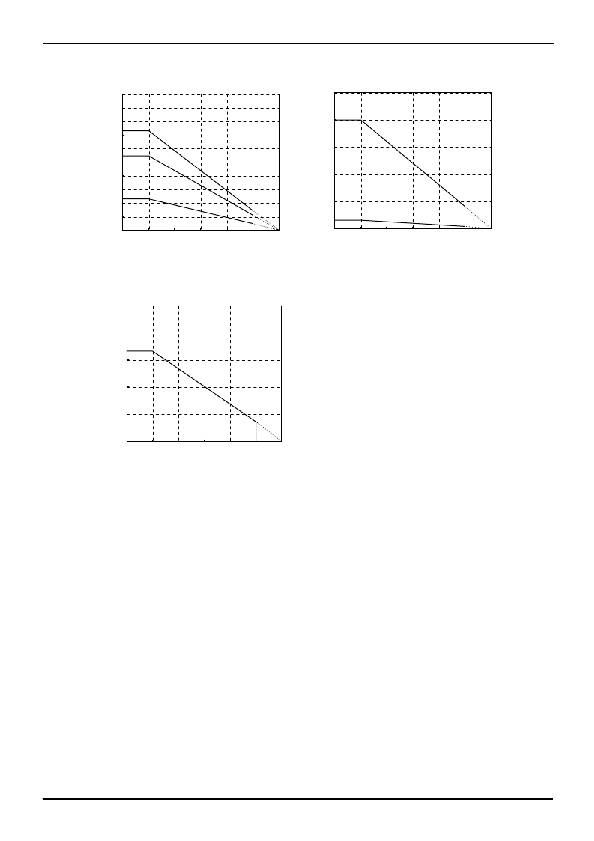
�Fig.28�
�Ambient� temperature:Ta(℃)�
�Fig.29�
�2.0�
�Mounted� on� a� Rohm� standard� board�
�Board� size� :� 70� ×� 70� ×� 1.6� ㎜�
�Copper� foil� area� :7� ×� 7� ㎜�
�TO252-5� θ� ja=96.2(� ℃� /W)�
�1.6�
�1.2�
�0.8�
�0.4�
�0.0�
�1.30�
�0�
�25�
�50� 75� 100�
�125�
�150�
�Ambient� temperature:Ta(℃)�
�Fig.30�
�When� using� at� temperatures� over� Ta=25� ℃� ,� please� refer� to� the� heat� reducing� characteristics� shown� in� Fig.28� through� 30.�
�The� IC� characteristics� are� closely� related� to� the� temperature� at� which� the� IC� is� used,� so� it� is� necessary� to� operate� the� IC� at�
�temperatures� less� than� the� maximum� junction� temperature� Tj� MAX� .�
�Fig.29� shows� the� acceptable� loss� and� heat� reducing� characteristics� of� the� TO220FP� package� The� portion� shown� by� the�
�diagonal� line� is� the� acceptable� loss� range� that� can� be� used� with� the� IC� alone.� Even� when� the� ambient� temperature� Ta� is� a�
�normal� temperature� (25� ℃� ),� the� chip� (junction)� temperature� Tj� may� be� quite� high� so� please� operate� the� IC� at� temperatures�
�less� than� the� acceptable� loss� Pd.�
�The� calculation� method� for� power� consumption� Pc(W)� is� as� follows:�
�Pc� =� (Vcc-Vo)� � Io� +� Vcc� � Icca�
�Acceptable� loss� Pd� ≦� Pc�
�Solving� this� for� load� current� Io� in� order� to� operate� within� the� acceptable� loss,�
�Vcc� :� Input� voltage�
�Vo� :� Output� voltage�
�Io� :� Load� current�
�Icca� :� Circuit� current�
�Io� ≦� Pd� –� Vcc� ×� Icca�
�Vcc� -� Vo�
�(� Please� refer� to� Fig.8� and� 20� for� Icca.� )�
�It� is� then� possible� to� find� the� maximum� load� current� Io� MAX� with� respect� to� the� applied� voltage� Vcc� at� the� time� of� thermal� design.�
�www.rohm.com�
�?� 2013� ROHM� Co.,� Ltd.� All� rights� reserved.�
�TSZ22111� ?� 15� ?� 001�
�12/17�
�TSZ02201-0R6R0A600080-1-2�
�25.July.2013� Rev.002�
�相关PDF资料 |
PDF描述 |
|---|---|
| ADP3335ACPZ-3.3-RL | IC REG LDO 3.3V .5A 8LFCSP |
| TC1055-2.5VCT713 | IC REG LDO 2.5V .1A SOT-23A-5 |
| GBB30DHBN | CONN EDGECARD 60POS R/A .050 SLD |
| AP131-15WG-7 | IC REG LDO 1.5V .3A SOT-25 |
| AP131-15WG-7 | IC REG LDO 1.5V .3A SOT-25 |
相关代理商/技术参数 |
参数描述 |
|---|---|
| BA00CC0WTE2 | 制造商:ROHM 制造商全称:Rohm 功能描述:2A/1A Variable Output |
| BA00CC0WT-E2 | 制造商:ROHM 制造商全称:Rohm 功能描述:2A/1A Variable Output LDO Regulators |
| BA00CC0WTTR | 制造商:ROHM 制造商全称:Rohm 功能描述:2A/1A Variable Output |
| BA00CC0WT-TR | 制造商:ROHM 制造商全称:Rohm 功能描述:2A/1A Variable Output LDO Regulators |
| BA00CC0WTV5 | 制造商:ROHM 制造商全称:Rohm 功能描述:2A/1A Variable Output |
发布紧急采购,3分钟左右您将得到回复。